Simple Cylinder Circuit Starts To Overheat When the Directional Valve Was Changed
By Robert Sheaf, CFPAI/AJPP, CFPE, CFPS, CFPECS, CFPMT, CFPMIP, CFPMMH, CFPMIH, CFPMM, CFC Industrial Training.
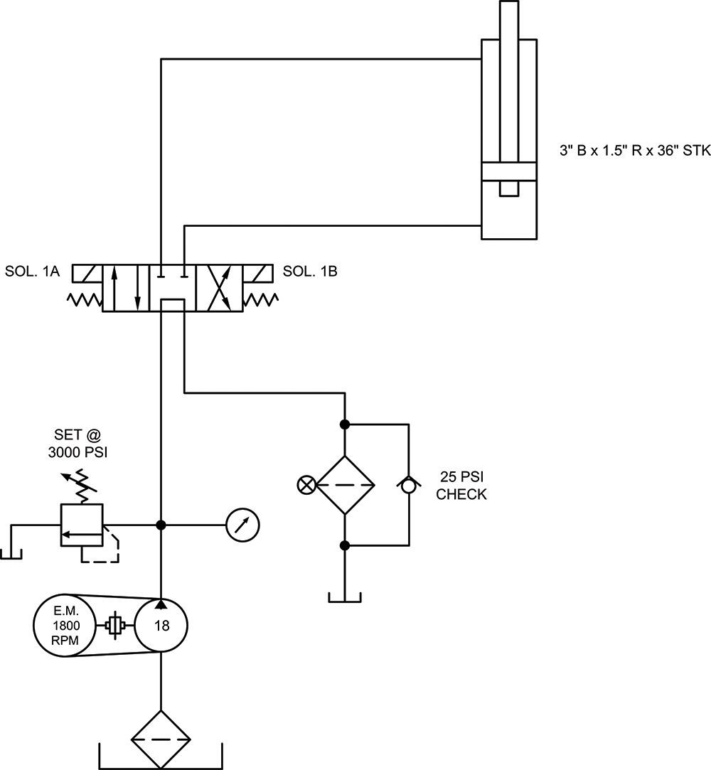
The circuit shown worked well for 6 months and the directional valve started sticking and needed to be replaced. The problem was found to be a matching chip that somehow showed up in the direction valve causing the valve to stick often. The customer called in their local hydraulic distributor for help getting a new valve. The distributor sent over a new employee that had some experience in hydraulics and felt he would be fine since it was a simple task.
The D-05 valve was an offshore brand the distributor did not recognize so he sourced a brand they had in stock that had the same spool configuration and D-05 pattern. They thought all was fine cycling the machine, but the system started to overheat. The technician from the distributor showed the customer the literature on the valve that showed on the front cover that the valve was rated for 25 GPM and when the cylinder retracted, it only flowed approximately 24 GPM. He felt the valve should not be the problem.
Any thoughts on what the problem might be?

See Solution
Robert Sheaf has more than 45 years troubleshooting, training, and consulting in the fluid power field. Email rjsheaf@cfc-solar.com or visit his website at www.cfcindustrialtraining.com. Visit fluidpowerjournal.com/figure-it-out to view previous problems.


