The Negative Effects of Over-Pressurization
Power transmission in a hydraulic system is a product of flow and pressure. It follows that the power rating of a hydraulic pump or actuator is a product of its ability to produce or absorb flow, and its maximum pressure rating. But what happens to hydraulic components if you screw-in that pressure-control device an extra quarter turn and operating pressure starts to exceed design limits?
The system won’t necessarily blow-up with a bang, but damage caused by over-pressurization can manifest itself in a number of ways, including
- Loss of Lubrication
- Valve Plate Separation
- Mechanical Damage
Loss of Lubrication
One of the variables that impact the creation and maintenance of hydrodynamic lubricating films is load. Hydrostatic force, and therefore load, is the product of pressure and area (F = P x a). This means that increasing operating pressure increases the load on lubricated surfaces. If operating pressure exceeds design limits, loads can increase to the point where boundary lubrication and two-body abrasion occurs—all other things equal.
Cylinder Barrel and Valve Plate Separation
In axial and bent-axis piston pump and motor designs, the cylinder barrel is hydrostatically loaded against the valve plate. To maintain full-film lubrication between the rotating cylinder barrel and the stationary valve plate, the hydrostatic force holding the two parts in contact is offset by a hydrostatic force acting to separate them. This is achieved by making the effective area of half the total number of piston bores slightly larger than the effective area of the pressure kidney in the valve plate.
The higher the operating pressure, the higher the hydrostatic force holding the cylinder barrel in contact with the valve plate. If operating pressure exceeds design limits, however, the cylinder barrel will separate from the valve plate. This is illustrated in Fig. 1.
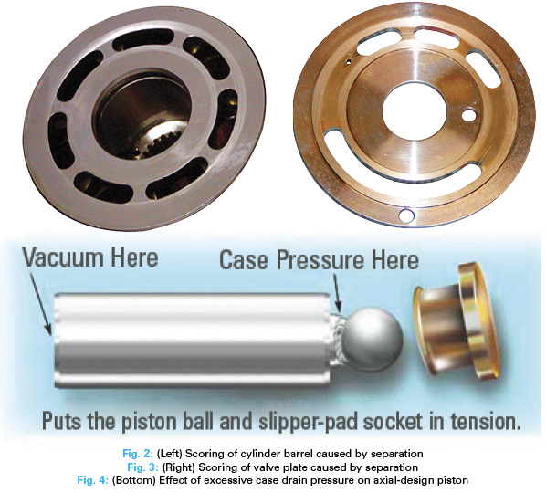
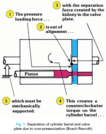 Design geometry prevents perfect alignment of the opposing hydrostatic forces, and this misalignment creates a twisting force (torque) on the cylinder barrel. During normal operation, this torque is supported by the drive shaft (axial designs) or center pin (bent-axis designs). If operating pressure exceeds design limits, the magnitude of the torque created causes elastic deformation of the drive shaft or center pin. This allows the cylinder barrel to tilt, bearing hard against the outlet side of the valve plate and separating from the inlet side. Once separation occurs, the lubricating film is lost, and the resulting two-body abrasion damages (scores) the sliding surfaces of the cylinder barrel (Fig. 2) and valve plate (Fig. 3). Erosion of the kidney area of the valve plate can also occur as high-pressure fluid escapes into the pump’s case at high velocity. This surge of flow into the case can cause excessive case pressure, resulting in shaft seal failure.
Note that valve-plate separation can also occur at operating pressures within design limits due to distortion (loss of flatness) of the valve plate, over-speeding, or excessive wear of the cylinder barrel drive-spline in axial designs.
Mechanical Damage
Over-pressurization can result in hose and seal failure, and mechanical failure of parts in pumps, motors, cylinders, and valves.
The effect of excessive pressure in the case of an axial pump or motor is the same as excessive vacuum at the inlet. Both conditions put the piston ball and slipper-pad socket in tension during intake (Fig. 4). This can cause buckling of the piston-retaining plate and/or separation of the slipper from the piston, resulting in catastrophic failure.
In radial-design motors, high case pressure can cause the pistons to be lifted off the cam. This can occur in operation during the outlet cycle. The pistons are then hammered back onto the cam during inlet, destroying the motor. If residual case pressure remains high when the motor is stopped, loss of contact between the pistons and cam can allow the motor to freewheel, resulting in uncontrolled machine movement.
High pump or motor case pressure also results in excessive load on the lip of the shaft seal. This causes the seal lip to wear a groove in the shaft, which eventually results in leakage past the seal. If case pressure exceeds the shaft seal’s design limits, instantaneous failure can occur. The subsequent loss of oil from the case can result in damage through inadequate lubrication.
Common causes of over-pressurization include faulty or incorrectly adjusted pressure-control devices such as pressure-relieving and pressure-reducing valves, and variable-pump pressure compensators. Uncontrolled decompression, thermal expansion (in load-holding circuits), or back flow through check valves or logic elements can cause pressure transients (spikes). In systems that experience rapid changes in load, the reaction time of the system’s pressure-control devices may not be fast enough to prevent the occurrence of pressure transients that exceed design limits. Problems associated with excessive case pressure can usually be avoided by connecting piston pump and motor case drain lines directly to the reservoir through dedicated penetrations.
Brendan Casey is the founder of HydraulicSupermarket.com and the author of Insider Secrets to Hydraulics, Preventing Hydraulic Failures, Hydraulics Made Easy, Advanced Hydraulic Control, and The Definitive Guide to Hydraulic Troubleshooting. A fluid power specialist with an MBA, he has more than 20 years experience in the design, maintenance, and repair of mobile and industrial hydraulic equipment. Visit his website: www.HydraulicSupermarket.com.






like