Understand Flow Control Valves

Fig. 1-21: Orifice Plug in Fitting
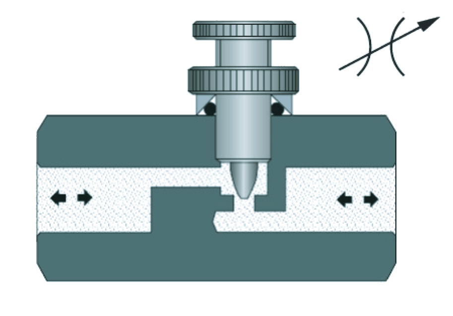
Fig. 1-22: Needle Valves Restrict Flow in Both Directions
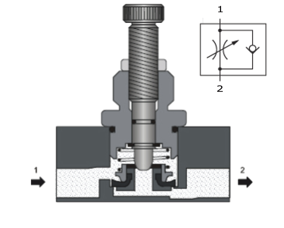
Fig. 1-23: Flow Controls
Restrict flow in one direction; 1-2. Free flow in opposite direction; 2-1.
The terms speed control and flow control are often used interchangeably to identify a valve with the primary function of limiting the velocity of an actuator. The process of limiting actuator velocity by restricting flow with an orifice introduces a pressure drop (ΔP) which may require an increase in supply pressure, depending on actuator type. Increasing the pressure also has an impact on the volumetric flow rate.
Flow controls commonly used in pneumatic systems are meter-out. The actuator speed is limited by restricting the air flow as it exits the component. This method will more effectively control overrunning loads. The meter-out flow control can al
so be installed on the exhaust port of the directional control valve. However, the load may jump if the actuator or piping has a large volume of de-pressurized air that will compress before being forced out the restriction. Meter-in flow controls will be used for components that do not have an exhaust port, such as a single acting spring return cylinder, for other applications where the load is constant, or if high back pressure would be detrimental to the component function.

Fig. 1-24: Flow Control Valve

Fig. 1-24: Flow Control Valve

Fig. 1-25: Flow Control Pattern
Safety tip: Caution should be used when applying meter-out flow controls as load induced pressures could cause the rod end pressure to become intensified and this pressure could exceed the maximum pressure rating of the cylinder.
The simplest flow control is a fixed, non-adjustable orifice. One method is to drill a properly sized hole in a threaded plug or set screw, see Fig. 1-21. The plug or set screw is then installed into a component port below the conductor fitting. In other cases the orifice plug is screwed into a threaded opening in the fitting. The design intent is to insure that the adjustment is not tampered with or removed. This convenient method of adding an orifice is sometimes overlooked when servicing equipment. If the fitting is replaced or improperly installed on a different port, the resulting fault may consume significant troubleshooting time to identify the cause.
Needle valves are adjustable orifices that restrict flow (speed) in both directions (Fig. 1-22). Flow controls (Fig. 1-23) are adjustable orifices with an integral check valve to permit flow (speed) control in one direc-tion only and reverse flow with minimal restriction.
The most common flow control used is a needle valve integrated into a fitting. A bypass check valve will also be integrated in the fitting to permit free reverse flow. The direction of free flow should be indicated on the body of the fitting. Depending on the application and location, the fitting may be used for meter-in or meter-out functions. The adjusting knob may have a locking portion to prevent vibration from causing the adjustment to change.
If the flow control fitting is installed on the exhaust ports of the directional control valve, a reverse flow check valve is not required, but may be used because it is often included as an integral part of the flow control fitting. •
Test Your Skills
1. If you are lowering a vertical load, the best solution to control cylinder speed would be:
a. Meter-out.
b. Meter-in.
c. Pressure regulator.
d. Pressure compensated flow control upstream of the directional control valve.
e. Pilot operated check valve.
2. A speed control on the exhaust ports of a 5/3 directional control valve:
a. Requires both speed controls to be adjusted to the same setting.
b. Requires a reverse flow check valve only for the cap end of the cylinder.
c. Requires a reverse flow check valve only for the rod end of the cylinder.
d. Does not require a reverse flow check valve.
e. Requires a meter-in speed control.
See the Solutions

