Use Protection
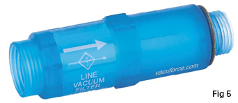
Centralized vacuum systems, where a single vacuum generator is used (Fig. 1 and Fig. 2), more often than not utilize a single vacuum filter. These two systems offer the user the same lifting capacity, but Fig. 2 has a dual circuit. This is useful if handling one or two parts, depending on the machine operation, or parts of a different area footprint. The filter shown in Fig. 5 is typical of this type of larger filter unit.
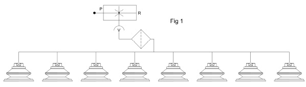
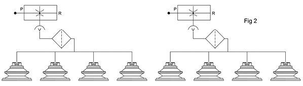
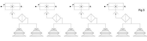
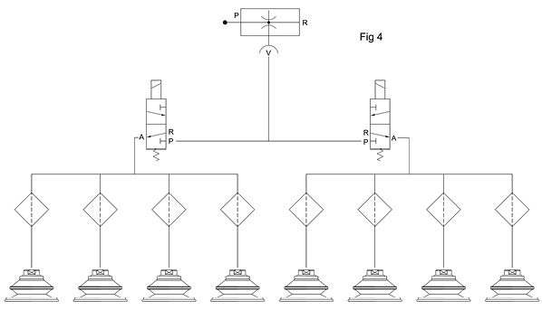
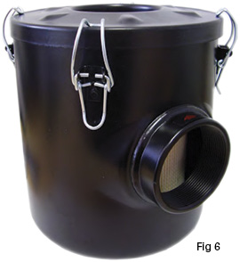
Fig. 3 shows a vacuum circuit where only two cups are being used per vacuum generator. This could be because the distance between each pair of cups is great and this system offers better control, or the cups are being used at different times. Even so, filtration should be used to prevent impurities from entering the vacuum generator. Fig. 6 shows a much more compact filter, which would typically connect directly to the inlet of each vacuum generator as shown.
 In Fig. 4, there are two vacuum circuits sharing the same vacuum generator, however, in this application, the dust or debris could interfere with the vacuum control valve. Therefore, individual filters are installed on each vacuum cup.
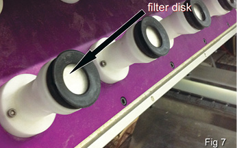
The first way to achieve this would be a filter disk installed directly inside the vacuum cup, as shown in Fig. 7. This prevents all impurities from entering the vacuum system. This type of filter, although effective, does not offer the user indication of filter condition. These types of filter “disks” can clog quite easily but still visually appear to be clean. This could lead to unreliable operation of the machinery.
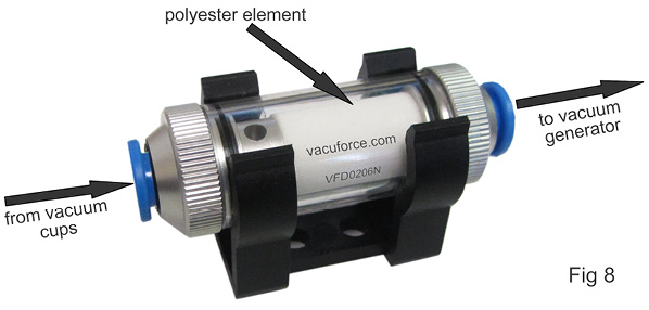
 A potentially more suitable filter would be one that offers easy visual inspection and, of course, cleaning or element replacement. Fig. 8 shows this type of filter and its internal element. It can be seen easily by the operator, yet its small size can enable close installation to the actual vacuum cup.
Of course, central point filtration, as shown in Fig. 1, is the better solution, offering easy maintenance and inspection by the vacuum user. Because of the size (filtration surface area) of the filter elements used in central point filters, the time between element change and inspection periods is extended. This type of filter system is often not the most suitable, however, particularly if components other than the vacuum pump require protection from debris in the application.
However, in Fig. 4, if the filter were placed between the generator and control valves (a single filter), it would act as a reservoir and in fact offer a quicker cycle rate, because as soon as the solenoid valves actuate, immediate vacuum is available to the cups. This is based on positioning of the valve relative to the cups and so on, but if the valves are resistant to dirt in the application, this could offer the user a better solution than the typical systems illustrated.
Whichever circuit is selected, the fundamental task has been achieved: to protect precision and potentially expensive apparatus from being damaged by debris found in most vacuum-handling applications.
This article is intended as a general guide and as with any industrial application involving machinery choice, independent professional advice should be sought to ensure correct selection and installation.
By Daniel Pascoe, Davasol Inc.
Vacuforce LLC is a manufacturer and distributor of vacuum components and systems for industry in North America. Vacuforce can be reached via its website (www.vacuforce.com) or directly at sales@vacuforce.com.Illustrations and 3D models supplied by Daniel Pascoe at Davasol Inc., an industrial distribution branding company. Daniel can be reached at dpascoe@davasol.com.
Share this information.
Related Posts


Sponsor

Sponsors