Vacuum Basics
By Richard Throop, CFPS
 Vacuum often seems like a mystery or “black art,” but vacuum is actually quite simple. When we talk about vacuum, we are talking about operating in the pressure region below atmospheric pressure (14.7 psi absolute at sea level) instead of above atmospheric pressure. The same principles and laws that work within pneumatics, such as Pascal’s Law and Boyle’s Law, apply equally to vacuum.
Atmospheric Pressure
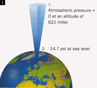
The weight of the various layers of atmosphere being held toward the earth by gravity is sufficient to develop approximately 14.7 psia at sea level. Naturally, as elevation increases, the atmospheric pressure decreases (Fig. 1).
Vacuum, Absolute, and Gauge Pressure
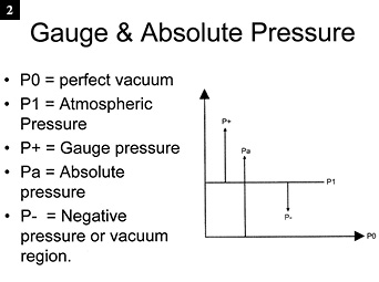 In order to understand vacuum pressure measurement, one first needs to understand the difference between absolute pressure (PSIA) and gauge pressure (PSIG). Although PSIA and PSIG are slightly different, they are two methods of measuring pressure, the difference being the starting point. Absolute pressure measurement starts at a perfect vacuum (no air molecules) while gauge pressure starts at atmospheric pressure (Fig. 2).
As stated earlier, vacuum is defined as the pressure region between P1 and P0. To measure absolute pressure (PSIA), we start at P0 and move up to and often beyond P1 (14.7 psia or 0 psig) into the positive pressure range. Positive pressures (P+) can be expressed in gauge pressure (PSIG) or absolute pressure (PSIA). Just add 14.7 psi to gauge pressure to determine the absolute pressure.
Vacuum Pressure Scales
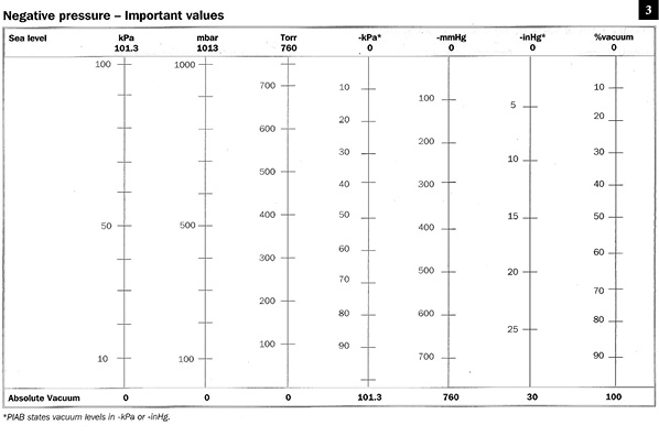
Vacuum pressure is often referred to as “negative pressure” or “sub-atmospheric pressure.” Several different scales are used for measuring vacuum, depending on the industry and application. The designation “mbar” is used in meteorology to allow expressing very minute changes in atmospheric pressure. The designation “-inHg” is often used to express the pressure level available for holding and material-handling applications. “Torr” and “-mm Hg” both split one atmosphere (14.7 psi) into 760 parts, but Torr starts at a perfect vacuum and moves up to atmospheric pressure, while –mmHg starts at atmospheric pressure and moves toward a perfect vacuum (Fig. 3). Vacuum measurement can also be expressed using the absolute pressure scale (0-14.7 psia).
Suction
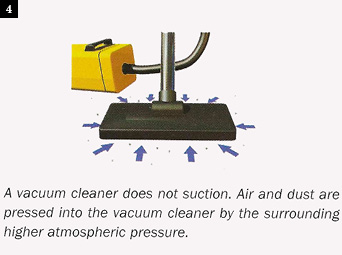 A vacuum cleaner does not suction. Air and dust are pressed into the vacuum cleaner by the surrounding higher atmospheric pressure (Fig. 4).
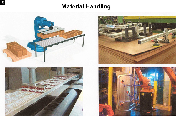
Material Handling
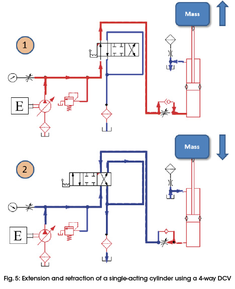
Vacuum is used extensively in material handling because of its ability to handle a large range of part sizes and materials without having to mechanically encapsulate them. Material-handling applications include but are not limited to stacking, de-stacking, palletizing, de-palletizing, and pick-and-place applications (Fig. 5). Materials that can be handled with vacuum range from sheet metal and plastic to cardboard or even wood. One major advantage of utilizing vacuum is that only a soft resilient material (vacuum cup) actually touches the part, reducing or eliminating potential part marking or container damage.
Vacuum and Hydraulics
Understanding vacuum is important to anyone working with hydraulics. Unless the hydraulic pump has a flooded inlet (reservoir above the pump), vacuum principles are at work. When a pump draws fluid from a reservoir situated below, it creates a vacuum at the pump inlet. The higher atmospheric pressure then forces the fluid up into the pump inlet. If the level of vacuum necessary to draw the fluid into the pump inlet is excessive, air bubbles will be drawn out of the fluid and cavitation will result as the bubbles collapse inside the pumping chambers under pressure.
Creating Vacuum
Over the years industry has developed numerous methods of creating a vacuum. Shown below are some of the more common methods used in industry.
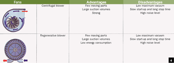
Blowers
See Fig. 6.
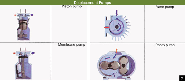
Mechanical Vacuum Pumps
Mechanical vacuum pumps employ similar technology and principles (Boyle’s Law) as those used in and air compressors (Fig. 7).
Compressed Air-Driven Vacuum Pumps
Compressed air-driven pumps operate on the Bernoulli’s principle. This principle describes a theorem that if air is forced through a transducer placed inside a hollow tube, it produces a reduced pressure by forcing the compressed air through a limiting orifice into a channel. When the compressed air passes through the orifice, it expands, increasing its velocity before it enters the channel section. Hence, a region of negative pressure (vacuum) is developed just past the orifice.
Single-Stage Ejectors
See Fig. 8.
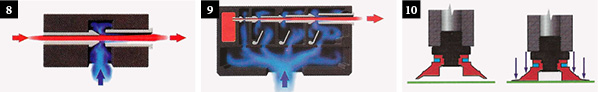
Multi-stage Ejectors
As venturi technology improved, manufacturers were able to optimize venturi design to achieve high flow, low vacuum level, and higher level of vacuum with even less compressed air flow. The modern multi-stage ejector combines multiple nozzles together to provide a good combination of high flows and relatively high levels of vacuum (Fig. 9).
Vacuum Cups
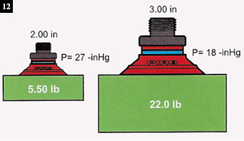
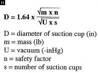 Lifting Force and Energy Requirements (Figs. 10 and 12): Due to the significant increases in pull-down time and energy requirements to achieve vacuum levels above mid range (-15-18″ Hg), it is generally recommended using larger or more vacuum cups to achieve greater total surface area (if the application permits), which will allow use of lower levels of vacuum (under -18″ Hg) while still achieving the same lifting force. The theoretical lifting/holding force for a vacuum cup is defined by F= (V x A x .491)/ SF.
 Where:
F = force in pounds
V = vacuum level –inHg
A = area of the cup
SF = safety factor
A = actual surface area (not diameter) of the cup in square inches in the collapsed state. Usually the safety factor ranges from =>2.
The preferred method of vacuum cup selection is to use the manufacturer’s catalog, which charts the lifting force of various vacuum cups at different levels of vacuum, as well as their lateral force capabilities, based upon actual testing. (See Fig. 11 for the formula for determining the diameter of cups.)
Lateral Forces
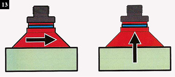 Always consider lateral as well as lifting forces on the vacuum cup, particularly if the load will be in a vertical orientation, or if the load is horizontal but being transferred rapidly where acceleration and deceleration forces are present (Fig. 13).
Centralized Vs Decentralized Systems
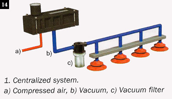 A centralized vacuum system offers the simplicity of a single pump, filter, and vacuum switch (Fig. 14).
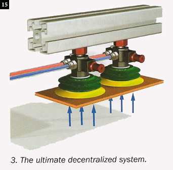
Decentralized System
A decentralized vacuum system (Fig. 15) utilizes several smaller individual vacuum generators, often one for each vacuum cup. When lifting applications represent a potential hazard, such as large, heavy, or sharp objects, a decentralized system provides additional safety due to redundancy. A decentralized system typically has two or more vacuum pumps and multiple vacuum cup zones. When handling large, heavy objects or sharp objects, accepted practice is to stagger the cups, then oversize the cups and pumps, so even if one zone doesn’t hold, the remaining zone(s) will still have enough lifting force to hold the part securely. A newer version of decentralized systems is the “vacuum gripper,” which provides redundancy and the convenience of having the vacuum generator, cup, and mounting apparatus all in one compact integral unit.
 Some Other Uses for Vacuum
- Evaporation
- Drying
- Degassing
- Mixing
- Chucking (holding parts)
Best Practices for Vacuum Systems
Considerations on implementing best practices for vacuum lifting/holding systems:
- Filtration. Filters are usually recommended between the vacuum cup and the vacuum source. Use a filter recommended for vacuum service to minimize pressure drop. Oversize the filter if you are expecting significant contamination. For compressed air-driven vacuum pumps, supply clean, dry air. An air-line filer is normally recommended, along with a coalescent filter if there is any oil contamination in the supply line. Some vacuum cups are available with internal screens to provide some coarse filtering of chips. If cups with screens are used, it is advisable that the circuit be configured for an air purge of the screens and cups every cycle.
- Vacuum transducers. Preferred methods of monitoring vacuum level (particularly with anything that might present a safety hazard) would be a vacuum switch or transducer to assure an adequate level of vacuum has been attained prior to attempting any lifting or holding of parts for machining. The connection point for the gauge or vacuum switch should be as close as possible to vacuum cup(s) to achieve the most accurate reading.
- Manual monitoring: In addition to any switches or transducers, add a vacuum gauge in a readily visible spot to provide easy visual monitoring of the vacuum system.
- Line sizes. Line sizing is extremely critical with vacuum, more so than pressure lines, since with vacuum we typically operate at less than 14.7 psi. If the connectors and conductors are too small, the pressure drop will cause a corresponding reduction in the available vacuum pressure and a reduction in holding force. If the lines are too large, cycle time will be sacrificed due to having to evacuate the excess volume.
The author would like to thank Piab.com for providing illustrations for this article.
Share this information.
Related Posts
Motion Control of a Single Actuator Against a Resistive Load

Stepper Technology Boosts FireFighting Efficiency

Land & Sea: Adapting Land-based Pressure-sensing to Deepsea Technologies

The Case for Using Radio Frequency Remote Controls in Mobile Machines
Fluid Power Electronic Controls Specialist (ECS) Certification Upgrade

Next-Generation Aerospace Sensors Respond to New Demands
Sponsor

Sponsors