Vacuum Pick and Place in Molding
The following is an opinion article written by Dane Spivak of Davasol Incorporated, an industrial brand management firm with many clients, including Vacuforce LLC, which partnered in the writing of this article. Contact Dane Spivak by email at dspivak@davasol.com.
Vacuum pick and place, or gripping, is common practice in the manufacturing of molded products. It serves many versatile purposes in processes including mold extraction, sorting, packaging, and trimming to name a few. This article discusses a variety of vacuum products and design techniques used throughout the industry.
Vacuum cup bellows
 There are thousands of vacuum cups available from numerous manufacturers, so deciding which cup works best can be overwhelming. The purpose of a vacuum cup is to create a seal against the product surface, which in turn generates a lifting or gripping force. Since cups by nature wear and need to be replaced regularly, users prefer affordable long-lasting cups. Cups may need to be replaced daily, or they may last many months, depending on the application and model.
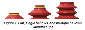
The vacuum cup model affects the performance and durability of the unit. The bellows of the cup is generally the focal point of the design. We can categorize the cups as being flat, single bellows, or multiple bellows as shown in figure 1.
 If we consider cups to be from the same manufacture and material, a flat cup usually provides the longest life; it is most stable, allowing the cup to absorb less stress forces. This allows the lip to wear at a slower rate, and therefore replacement is less frequent. However, molded products are often curved or textured, so a flat cup would be unable to seal against such a surface. In these cases, bellows cups are used since the body acts like an accordion for height and angular compensation. The more bellows, the more compensation, but less stability when gripping the load. Also, a bellows design typically is less durable due to the continuous compression of its natural rest state. A single bellows cup is the most popular choice; it offers a good balance between durability and compensation. The compensation of bellows cups is also used for compensation of the machine actuation when cups contact the part being handled.
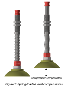
On the topic of height compliance, using spring-loaded level compensators is a popular method of adding to height compensation to the machine actuation. Figure 2 demonstrates how the spring in the body compresses as the rod moves through the body. Most level compensators are designed for vertical compliance only, though it is not uncommon in the molding industry to see them angled where necessary when handling lightweight products. Level compensators are also a convenient method of mounting the cups and providing a vacuum outlet port.
Vacuum cup materials
 In molding, the key technical factors in vacuum cup materials are Shore A durometer rating (hardness), high temperature limits, and FDA compliance. Common cup materials include nitrile (NBR), polyurethane, vinyl, and silicone. The following paragraphs touch on each material individually and how it relates to the key factors. Note that the following information is typical of what is found in the industry, though there are, of course, potential variations.
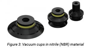
NBR cups are usually rated 55 to 60 Shore A durometer. This is considered to be a relatively harder rating for a vacuum cup on the durometer scale of rubbers. Because NBR cups are harder, they do not deform (offering compliance to the part being handled) as well as a lower-durometer-rated cup. This means it may not provide as good a seal if the surface has curvature or has a pronounced texture. NBR cups are rated for temperatures up to approximately 200°F, so it will not handle hot molded parts. It also is not FDA compliant. NBR is a good basic material choice; it is durable due to its higher durometer and is relatively lower in cost. NBR can usually be identified by its most common color, black, as shown in figure 3.
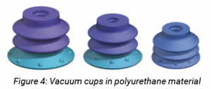 Polyurethane (PU) cups range in durometers of 30 (soft) to 70 (harder). PU cups do not have a broad temperature range—approximately 50°F to 120°F. PU is not considered FDA compliant. This material is known for its good durability, though it tends to cost more than a rubber cup. Since NBR is lower in cost, it is often chosen over PU, though the low durometer option of PU makes it an attractive choice. PU vacuum cups come in a range of colors, so it can be difficult to identify them in the field compared to other materials. A dual-durometer-construction PU cup and multiple color options are usually a good indicator. Examples are shown in figure 4.
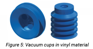 Vinyl vacuum cups have an approximate hardness range of 45 to 55 durometer. The maximum temperature threshold is around 125°F. Vinyl can be FDA compliant. Vinyl material is not the longest lasting vacuum cup material; it tends to “work harden,” though its cost is low so it is a popular choice. The majority of vinyl cups used in industry are translucent blue, as shown in figure 5, which makes them easy to identify. However, some PU cups can have similar colors.
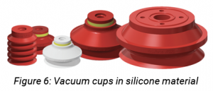 We save the best for last as we move to silicone vacuum cups. Silicone lands in the durometer range of 40 to 50 for most vacuum cups. Its softness is ideal for curved and textured surfaces, though it can take away from its durability. Despite being softer, silicone offers reasonable cup longevity. Silicone cups handle temperatures up to 400°F, so it is the material of choice when it comes to vacuum gripping hot molded products. Silicone is often chosen over NBR even if the molds are within the acceptable temperature range for both, since silicone has developed a reputation as the “go to” material. Additionally, silicone is FDA compliant, which makes it necessary for many applications in the food, beverage, and medical industries. Silicone is often identified by its white and red colors, as shown in figure 6.
Venturi vacuum generators and compressed air management
Venturis, also referred to as generators or ejectors, use compressed air to produce vacuum. This technology is popular in vacuum gripping and pick and place for applications in molding. Electric vacuum pumps are also used, but venturis are often the preferred choice for point-of-use applications due to their simplicity, low cost, and small size. The following discusses different types of vacuum ejectors and how to minimize compressed air consumption in molding applications.
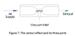 A vacuum generator produces vacuum by compressed air flowing through a venturi nozzle. The decreasing diameter of the nozzle increases the air velocity across the cavity, which creates a low-pressure pocket. This low-pressure area pulls or sucks in surrounding air, which is attached to the vacuum port. The venturi principle is named after its discoverer, Italian physicist Giovanni Battista Venturi (b. 1746). Figure 7 illustrates the venturi effect. Note that a venturi must have at least three ports to function, including the compressed air source, exhaust, and vacuum ports. Some units may have more ports for additional accessories, though it must include the aforementioned three.
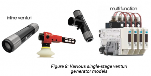 Single-staged venturis are units in which the venturi has a single orifice, as shown in figure 7. There are also multistaged venturis that have more than one orifice, which we will discuss later. Single-staged units are typically used to power a single cup or a handful at most. They are small and inexpensive. A typical single-staged venturi uses around 1 CFM of compressed air, though larger ones may consume 10 CFM or more. On average they have around a 1:2 ratio of vacuum flow to compressed air usage. They are not as efficient in producing vacuum flow as multistaged models. A variety of single-staged venturis are shown in figure 8. In molding, the cylindrical inline unit with the exhaust built into the body is popular. Multifunction units are a great way to consolidate vacuum sources and other system-related components. They can include pneumatic valves for on/off control, vacuum sensors for measurement, blow-off valves for quick release, and other control functions.
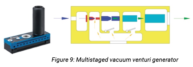 Multistaged generators contain more than one vacuum venturi, as the name suggests, with two- and three-stage units being the most common. The purpose of more than one stage is to use the compressed air consumption more efficiently. After the compressed air passes through the first venturi (red in figure 9), air is pulled from ambient, then this combined air flows through the second venturi (blue in figure 9), and this combined air flows through the third venturi (cyan in figure 9). Therefore the original air used in the first venturi collects “free air” through venturis two and three. This process allows for a better vacuum flow-to-compressed-air use ratio, which is the reason multistaged units are used instead of single staged. Three-staged models are generally the cut off, as using air after three stages becomes ineffective. Multistaged generators typically power multiple cups, depending on how much vacuum flow is required, but smaller units can also be used for single cups. Single-stage generators coupled to individual cups are sometimes chosen for their simplicity of installation despite being less efficient. Multistaged venturis are larger in physical size and higher in cost, which also becomes a contributing factor in model selection.
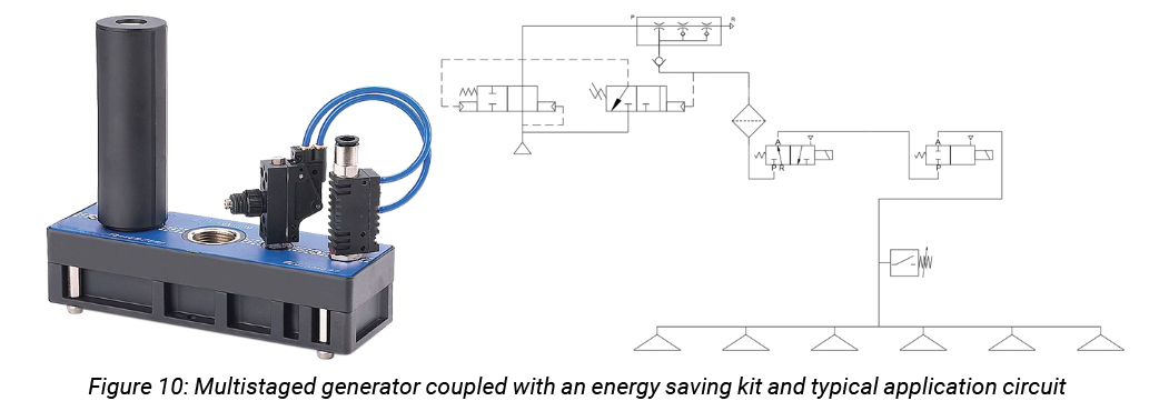
Depending on the application, further compressed-air-saving measures can be taken. Energy-saving kits (ESKs) can work in conjunction with vacuum generators. ESKs consist of a pneumatic valve to turn the compressed air supply on and off automatically, based on the vacuum level detected in the system by a vacuum sensor. When the vacuum level is high, the sensor signals the valve to shut off. If the vacuum level drops below the switch low setpoint, it signals the valve to turn back on and “charge up” the vacuum level of the system to its high setpoint. ESKs are only effective when the cups get a good seal on the product surface so that vacuum can be locked into the system when the generator is not running. This is feasible for many molding pick-and-place or gripping applications with vacuum cups. In a pick-and-place application, the venturi may only run a fraction of the time, even during the product transfer cycle, thanks to the ESK. This process can reduce air consumption up to 90%. ESKs require the system or venturi to have a check valve to lock in the vacuum, as well as a vacuum valve or blow-off to exhaust vacuum and release the product. An example of a multistaged venturi coupled with an ESK, along with a typical vacuum cup circuit, is shown in figure 10.
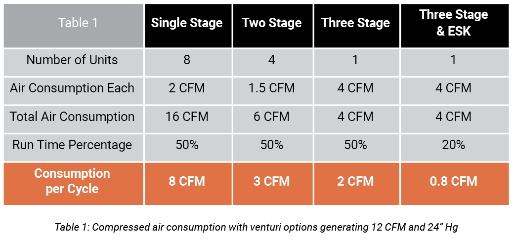
Table 1 demonstrates a simplified comparison between the many possible generator options previously discussed for an eight-cup application. All options generate around the same amount of vacuum flow and vacuum level. However, the air consumption differs drastically.
Table 1 suggests that the three-stage and ESK option uses considerably less compressed air than the single-stage option. This is particularly significant when many machines are used across a production facility.
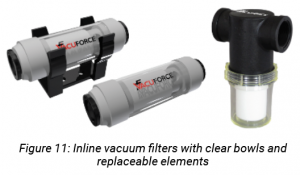 A quick note—vacuum filters are absolutely crucial to use with venturis. They filter out particulates before ambient air enters the generator body. Venturis have no moving parts other than air passing through, but the orifices are as small as 0.5 mm, which can clog easily without proper filtration. The same approach should be applied to the pneumatic compressed air source. Figure 11 shows common vacuum filters used in molding applications that have clear bowls for ease of visual inspection. The filter elements are also easy to clean or change.
Conclusion
This article covered vacuum-cup styles and cup material attributes. It also touched on different venturi types and compressed air reduction techniques. Many vacuum systems or designs throughout the molding industry may qualify for improvements. Each application is unique, and professional assistance should be sought for design recommendations.
Share this information.
Related Posts


Sponsor

Sponsors