Energy-Efficient Hydraulics: Variable Frequency Drives as Pump Prime Movers
It is obvious what we want to achieve with variable speed pumps: to save energy and reduce noise and possibly increase the power density of hydraulics. To explain only how to put the electro-hydraulic package together does not provide enough insight. The total hydraulic system functionality needs to be looked upon in the light of competing technologies.
In industrial applications, hydraulic pumps are usually driven with electric motors so the conversion to variable speed drives is more of an upgrade than a major modification. In mobile systems, hydraulic pumps are most often driven by internal combustion engines. It is more complicated to use variable frequency drives on mobile equipment because the electricity to drive a variable speed motor needs to be supplied by a generator or a fuel cell and then stored in batteries. While converting from the DC supply to AC for the motor is not technically difficult, adding the power supply would likely lead to a complete vehicle redesign. Nevertheless, it is worth looking at the paradigm shift of introducing variable frequency drives to electrically-generated rotary and linear motion.
Hydraulics is only one of several methods of power transfer. The so-called “electro-hydraulic actuator” may be an interesting solution in some special applications, but not a viable general solution in multiple motion applications. There is additional cost for converting electric power into hydraulic pressure and flow. If this conversion occurs for each of multiple actuators, it will not be cost effective. The conversion should be done in a central power unit and the cost spread over the multiple actuators.
There are different types of electric motors on the market including the induction motor, the permanent magnet motor, and the reluctance motor, each of which needs to be well understood by the hydraulic engineer putting the electro-hydraulic pump package together.
In hydraulic linear motion, the asymmetry of a single rod cylinder can be compensated with modern integrated regenerative valves. This needs to be considered to minimize the flow demand from the pump before laying out the electric drive and hydraulic pump package.
The beauty of a three-phase electric grid is the way it generates the rotating field of an electric motor. It only needs the determination of the number of poles in the motor to set the speed. If we insert a frequency inverter and make the speed variable within the lower and upper capabilities of the motor, we only need to choose the motor with the most suitable RPM range to drive our hydraulic pump. Typically the four-pole induction motor or the permanent magnet motor would be the preferred choice.
The motor cooling needs special consideration because it may be required to drive a hydraulic pump at speeds ranging from very low to very high. There are a variety of designs for cooling the electric motor that include heat dissipation through the housing surface, a cooling fan rotating with the motor, a separate cooling fan, and even fluid cooling of the housing. The most common for induction motors is the fan running with motor speed. This solution may be inadequate when running at full torque and low speed and so the cooling needs of the motor will need careful consideration.
There are a variety of hydraulic pumps on the market including gear, vane, and piston pumps. Their speed range under full pressure varies a lot with their frame size. Generally a smaller pump goes to higher maximum speed and creates less noise. The minimum speed depends more on the pumping principle than on the frame size. A hydraulic pump is lubricated by the hydraulic fluid. Most pumps need to rotate for proper lubrication and cannot stand still under pressure.
Motors with variable frequency drives as pump prime movers were introduced into the market with the internal gear pump. Small displacement pumps with low inertia can run with flow and pressure control from the motor. High-precision gear pumps that have a single pumping chamber, require strong bearings to keep the gear position within tight tolerances. The typical vane pump with its two balanced pumping chambers and interchangeable cartridge without bearings offers new opportunities. The cartridge can be integrated in a motor with an extended shaft and allows for an extremely compact package. Vane pumps are also available as double or triple pumps in a common housing and can work as a simple switchable pump combination in order to choose the smallest possible motor for the application.
A variable piston pump needs either to stroke in reverse flow direction to decompress, or alternatively, a pressure-compensated pump is used with a small relief, piloted by the pump controller. A combination of a fixed vane pump with its low losses at low pressure and a variable piston pump with its high efficiency at high pressure is very often the most energy-saving solution.
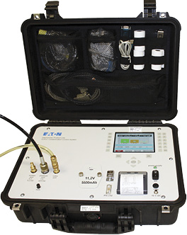
When putting together the electro-hydraulic package, consisting of drive, motor, and pump, all the inefficiencies get added up, and the target is to minimize. Good results cannot be achieved in a trial-and-error approach. An intelligent software tool is needed that has stored all the individual component efficiencies in relation to their parameters. At first the flow and pressure demand vs. time is entered into the so-called DriveCreater tool. A pump or pump combination is selected. The motor temperature is calculated at the given machine cycle in continuous-operating mode. The chosen motor requires a current, and hence a suitable drive is selected. Different solutions can be compared with regard to their consumed energy. A solution with inverter can be compared against running the motor straight from the grid. How much energy is saved in a specific application depends entirely on the machine cycle.
For the startup of the drive, a setup tool is helpful to reduce the amount of programming work. The motor data can be entered from the nameplate, and a preconfigured operating mode, e.g. accumulator charging, p/Q control, or other can be chosen.
About the Author: Dr.-Ing. Gerd Scheffel joined Towler Hydraulics Germany as chief development engineer for industrial valves and was involved in defining the international standards for slip-in cartridges. Following the acquisition of Towler, he joined Parker Hannifin as engineering manager for industrial valves in Europe. After running a mobile valve unit as operations manager, he became managing director of the Hydraulic Controls Division Europe, a division producing pumps, motors, valves, manifolds, power units, and electronics. He managed the division for 23 years. Since the beginning of 2012, he has worked as engineering manager of the Hydraulics Group Europe for Industrial Applications. Contact him at gerd.scheffel@parker.com.

