Closed-Loop Electro-hydraulic Control Aids Component Fatigue Testing
Fatigue analysis is a technique that is performed in R&D labs to understand the failure properties of a specimen in order to improve the reliability, quality, or cost of a manufactured product. Typically, the analysis starts by evaluating a series of mathematical equations, but then the results can be verified using real-world testing. Such is one of the processes being undergone by the NACCO Materials Handling Group (NMHG) Development Center in Fairview, Ore., one of the three research and development facilities for the Hyster® and Yale® lines of lift trucks.
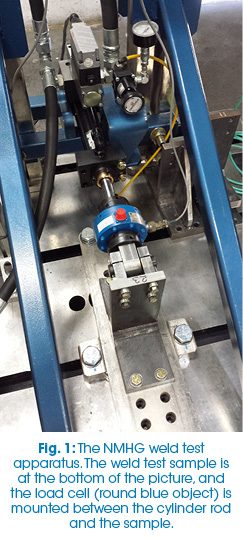 Fig. 1 shows the test apparatus developed by NMHG. The system uses one hydraulic cylinder with a 1.5″ bore, capable of exerting up to 2,500 pounds of force in either direction. As the figure shows, the test sample is a lever arm, approximately eight inches long, acted upon directly by the cylinder. Between the cylinder rod end and the sample is a load cell, which is used to monitor the force that is being applied. Embedded in the cylinder is a magnetostrictive linear-displacement transducer (MLDT), which is used to track the amount of deflection of the arm as the weld joint deflects.
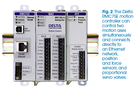
To control the cylinder, NMHG chose the RMC75E motion controller manufactured by Delta Computer Systems of Battle Ground, Wash. The controller (Fig. 2) connects directly to the load cell via a built-in analog interface and the MLDT via an SSI interface. The control output from the controller goes directly to a proportional hydraulic servo valve, allowing the controller to smoothly increase and decrease the force exerted by the cylinder. The motion controller is coupled via Ethernet to a PLC for supervisory control, and a PC for process monitoring and data logging.
To program the motion of the NMHG test platform, the RMC’s built-in sine wave motion function was used, with a frequency of two cycles per second. To ensure that the force applied hits the target value, the controller was set up to perform adaptive control of the hydraulics. The motion program captures the peak amplitudes every cycle, compares them to the force targets, and adjusts the offset and amplitude of the sine wave while ensuring that the system maintains smooth transitions in force levels.
In cyclic testing applications such as this, where achieving a particular amplitude and offset are more important than precisely tracking the entire waveform, adaptive amplitude control gives the user the ability to continuously adjust the amplitude of the target signal so that the amplitude of the actual signal is where it needs to be. For example, to achieve a sine wave with an actual amplitude of 1, the adaptive control may adjust the target amplitude to 1.5 and continue to adjust in order to maintain the correct actual amplitude.
“This adaptive control really shines as our test samples fatigue and the displacement increases,” said Saul Dyal, NMHG test engineer. “Prior to implementing adaptive control, we’d see an offset in our data and the system would struggle to hit the target force in one direction, thus decreasing the actual peak force. Now the motion controller adjusts the offset and amplitude as needed throughout the test to ensure we hit the desired peak forces every cycle, even as conditions change.”
One environment variable, for example, is a change in the temperature of the hydraulic fluid, which can affect how the system reacts to a particular control output from the motion controller. Another factor affecting system operation is the fact that, because the fluid volume is different on the rod side compared to the open side of the piston, the typical cylinder responds differently whether it is extending or retracting. The software needs to compensate for the area difference between the rod and blind end of the cylinder. “With Delta’s adaptive control, the system automatically adjusts to these changing conditions,” continued Dyal. “As a result, we’ve been hitting our force target to within +/-½ pound much of the time.”
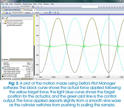
In tuning the system, the NMHG team used the RMCTools software provided by Delta. One of the most useful of these tools is the Tuning Wizard, which calculates gain values based on plots produced during a move. Fig. 3 shows a plot of approximately three test cycles of the weld test system. In the plot, the black curve is the actual force being applied over time, which precisely overlays a yellow curve representing the target force. The fact that the target force and actual force curves overlap signifies that the system is precisely tuned.
Tuning a hydraulic system involves a process of adjusting the gains (multiplier factors) of the proportional (P), integral (I), and derivative (D) factors in the control loop algorithm so that the actual motion of the system matches the desired motion. The NMHG team found system tuning to be difficult initially, largely due to inexperience with tuning hydraulic components. As experience was gained, the team developed a process in which the P and I gain values were set so as to get the actual force to approximately track the target force. Then they followed an iterative process of making a move, creating a plot, and using Delta’s Tuning Wizard to calculate gain values to fine tune the motion. The overall time to force tune the actuator was reduced to a few minutes using this technique.
The ability for an attached PC to precisely log parametric data during the course of a test allows the NMHG engineers to gain advance information on the performance of the system, including giving them the capability to see how a weld joint reacts before it fails. The team set up the test process to log data ten times per minute and was able to see that the position curve changes slope before a crack in the joint is visible.
The next steps for NMHG will be to gradually increase the complexity of the welded joints and use the test results to develop parameters for mathematical models that will be used to predict the life of various configurations. Ultimately, this should enable a reduction in the time needed for actual physical testing as the company improves its software models and catches potential fatigue issues prior to building physical prototypes.
New vehicle testing will always involve running completed units on the test track, but companies such as NMHG can improve their confidence in products’ long-term reliability by testing assemblies down to the level of how individual welds are accomplished.
For more information, visit www.deltamotion.com.
Share this information.
Related Posts


Sponsor

Sponsors