An Introduction to Hydro-Mechanical Transmissions
Fuel cost and the fuel-saving characteristics of continuously variable transmissions (CVTs) have increased the pressure to provide CVT capability to larger and larger off-road machines. Hydro-mechanical transmission architecture allows smaller hydraulic components to provide cost-effective CVT functionality to larger machines. As a result, the number of hydro-mechanical transmissions in the marketplace is growing.
A hydro-mechanical transmission schematic is conceptually simple with two parallel power paths (Fig. 1). The hydraulic path is made up of a pump and motor referred to here as a “variator.” The mechanical path is typically a shaft with maybe a gear or two. These paths are interconnected with ordinary mechanical transmission components such as gears, shafts, clutches, and at least one planetary. There are a very large number of interconnection possibilities. In a given design, it is the details of these interconnections that constitute the bulk of the intellectual property and the suitability to the target machine application.
Hydro-mechanical transmissions have been available in agricultural tractors for a long time. They are either standard or offered as an option (Fig. 2).
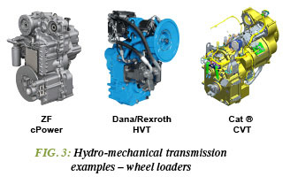
Hydro-mechanical transmissions have not generally been available in earthmoving equipment until now. The wheel-loader segment is thought to benefit the most from a CVT, and that is where the latest offerings can be found. The examples in Fig. 3 have been announced and are available now or will be shortly.
Three things differentiate given designs:
- First is the construction of the variator and its location, for example variable-displacement swashplate pump, fixed-displacement bent axis motor, internally mounted.
- Second is the type of coupling. Common terms are input coupled, output coupled, and compound split. While the particulars of this nomenclature are well beyond the scope of this article, it generally describes whether or not the transmissions input or output shaft is directly connected through a gear ratio to one of the variator shafts. In the case of compound split, neither variator shaft is directly connected.
- Third is number of ranges or modes. This is the number of different mechanical interconnections made between the mechanical and hydraulic paths by engaging and disengaging any clutches in the gear systems. Note that the type of coupling is not necessarily the same for each range or mode.
Consider the engine fuel map shown in Fig. 4. The vertical axis is engine power and the horizontal axis is engine speed. The peak of each contour indicates the maximum engine power for that fuel rate. The locus of these peaks defines the best engine speed for minimum fuel consumption.
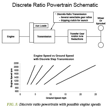
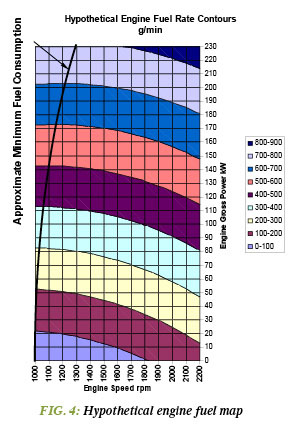 Consider the powertrain described in Fig. 5. The plot in the lower part of the figure indicates that for any given ground speed, there are only one or two engine speeds possible. It is unlikely that one of these speeds falls on the minimum fuel consumption line of Fig. 4. Furthermore, anticipated load changes, particularly if there are any difficulties in changing ratio, may lead an operator to choose a higher engine speed (higher fuel consumption) and/or slower ground speed (slower cycle time).
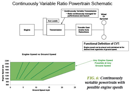
Consider the powertrain in Fig. 6. The plot in the lower part of the figure indicates that for a given ground speed, nearly any engine speed is possible and therefore can match the minimum fuel consumption engine speed shown in Fig. 4. The engine speed lines from the plot in Fig. 5 are included for reference. Because modern hydro-mechanical CVTs change ratio so well, there are few if any issues with load changes like there may be with discrete step transmissions.
While the information in this article may not prepare you to design a hydro-mechanical transmission, it will enable you to more readily recognize them and their potential benefits.


