A New Spin On An Old Idea
I am going to go out on a limb to make a suggestion. Now, for me, this is not all that unusual. I have been described as someone who thinks “outside the box” and have been accused of not even remembering where the “box” is anymore. In fairness, this is not a brand-new idea, nor is it entirely mine. I had an opportunity to read an article by Bård A. Harang of Hymatic AS, Trondheim, Norway, where he describes a reservoir that would provide a way to more efficiently keep the hydraulic fluid clean. The more I thought about his concept, the more potential benefits I could see. I am not using his words but, with his permission, I am using some of his thoughts.
In our Hydraulics 101 course we learned that there are four primary purposes for a hydraulic reservoir: to store hydraulic fluid, to allow gas bubbles to rise to the surface, to allow particulate to settle out, and to allow the fluid to cool. Experience has shown that it takes about two minutes for the average hydraulic fluid in a quiescent state to release the air and particulate it carries into the reservoir. This is the information that brought about the “rule of thumb” that a reservoir should be at least two times the average pump flow and if two is good, three or four would be even better. More fluid in the reservoir allows for a longer quiescent time. The longer the quiescent time, the more the bubbles, particulate, and heat can be removed. This seems to make good sense and has been the adopted standard of most industrial facilities and power unit designers and fabricators.
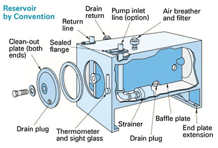
The typical hydraulic reservoir in an industrial facility is a rectangular container as in Fig. 1. A reservoir with this arrangement can be purchased as a standard item, and as a result, designers often simply determine the approximate reservoir capacity, order the next size larger, and leave it at that.
However, there are some issues with this design. Remember the four purposes of the reservoir? This design certainly does allow for the release of gas bubbles and the settling out of particulate, but where does the particulate go? It settles onto the bottom of the tank. The baffles and braces add places where the contaminants will collect. The clean-out plates are there to allow the periodic cleaning out of the reservoir, but it can be a nasty job and is often not part of a routine maintenance schedule. It requires the complete draining of the reservoir and then for someone to reach in (or crawl in) to the tank to scrub out the floor and the corners. The fluid will need to be stored and run through a filter cart when it is reintroduced to the reservoir. Consequently, the clean-out job does not usually get done until there is some other catastrophe that requires draining the reservoir. If the reservoir is not cleaned out, there is the danger of a sudden inrush of fluid that will stir up the sediment, which could then be drawn into the system through the suction line.
Another issue is the ability of this type of reservoir to allow the fluid to cool. Hydraulic fluid has a relatively low specific heat, which means it resists taking on or giving up heat. Fluid molecules moving through the center of the reservoir are essentially insulated from the exterior wall by all the other fluid in the tank. Even the fluid by the exterior wall has to deal with the resistance of carbon steel to transfer its heat to the atmosphere.
There are a couple of manufacturers who are now making reservoirs specifically designed for mobile equipment and that take an extremely different approach. The reservoirs are cylindrical in shape and hold a tiny fraction of the average pump flow. One company with whom I had a discussion uses a 5-liter reservoir for a 75-lpm pump flow. That is not a misprint. I am serious. They successfully use a 5-liter reservoir for a 75-lpm pump flow. The design takes the return line from the pump and causes it to spin around at high velocity toward the suction port. This actually causes a positive pressure at the suction port and assures good inlet conditions for the pump. The spinning motion causes a cyclonic effect that pulls the air bubbles to the center so they can exit through the vent cap. The benefits to this design are the decrease in size, the lower volume of fluid to be purchased, the reduced weight, and the limited amount of fluid that would be spilled in the event of a hose failure. The disadvantages are that the units provide no cooling, no filtration, and require an almost constant flow. Variable displacement pumps are not easily accommodated because, if the fluid velocity entering the reservoir is reduced, the cyclonic effect is less effective in removing the air. Large displacement cylinders are also a problem because there is not enough volume for the reservoir to breathe as the cylinders stroke.
I think there is a compromise between the traditional, rectangular reservoir and the tiny mobile reservoir that may better address the needs of both industrial and mobile equipment. It is still a cylindrical reservoir, but large enough to meet the other needs of the system.
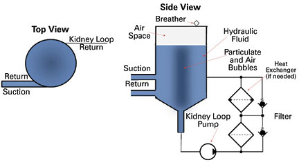
Given a cylindrical reservoir with a conical bottom as in Fig. 2 and with the return line entering tangentially to the tank, think about what happens. The return flow causes a gentle rotation of the fluid within the tank. Instead of a centrifugal force pushing the particles against the wall, a cyclonic effect produces a lower pressure in the center, drawing all the particulate and gas toward the middle of the reservoir and away from the inlet line to the pump. The gas escapes through the breather and the particulate drops to the bottom where it is drawn out to the kidney-loop system. A smooth seam where the cone is joined to the cylindrical tank prevents any of the sludge buildup found in the rectangular tank, and so there is no need for the scheduled clean out. This is what Bård A. Harang wrote about and has experienced in the field.
The additional value I see to this arrangement relates to heat exchange and the reduction in the necessary volume of the fluid. The returning fluid carries the heat generated by the inefficiency of the working system. Entering tangentially to the cylindrical reservoir, the fluid remains against the outer wall as it rotates around. This should result in a better heat exchange to atmosphere. A cylinder is stronger than a rectangular box, and so this reservoir can be made of thinner material. Making the reservoir out of aluminum dramatically increases the ability of the fluid to give up heat through the wall (aluminum has a specific heat of 0.12 as compared to carbon steel with a specific heat of 0.22). All this means is that the amount of fluid to be stored can be reduced because there is no need for the long quiescent time. The reservoir can be sized simply for the change in volume used by the actuators and/or supplying the accumulators.
Another advantage is that the cylindrical reservoir has a smaller footprint than a rectangular reservoir of the same capacity. The combination of a smaller footprint, a fraction of the required fluid that needs to be purchased, and the potential for eliminating or reducing the size of the heat exchanger may make it possible to have a very competitive installed cost.
Think about it.


Cyklontank, as it is now called, has actually become quite a mature product, even adressing different flows and volumes when hydraulic cylinders are used.
Nils Harald Flaa at the recently opened PMC Servi office in Houston is an expert on the recent developments: nsf@pmcservi.no.
You may also like to check out this link:
http://www.pmcgroup.se/Products/Product-Cases/Cyclone-tank-means-less-weight/
Bosch Rexroth also has cyklone tanks for hydrostatic drives, but I’ve been told that such drives have been used on fan drives on Volvo buses for several decades already:
http://www.boschrexroth.co.uk/country_units/europe/united_kingdom/en/company/news_events/press_releases/DCGB_Machinery_Engineering_Applications/Bosch_Rexroth_Cyclone_Hydraulic_Oil_Tanks/index.jsp
Completely agree with this design. Coming from 11 years of well drilling background and switching 15 years ago to Hydraulics, I see a lot of similarities with the drilling mud cleaning installations (hydro-cyclone batteries) used to remove sand, silt and other small particulates. What we need actually is to achieve two things: convince the designers to bring this into new systems and (maybe harder) convince the end-users of the systems on the efficiency of this design.
I am embarrassed to say that I just now read your comment on the article I wrote on the cylindrical reservoir. We are just starting this blog for the Journal and we decided to post a couple of my articles do generate discussion. When I re-read them, I saw your comment. Thank you.
In the next article “Outside the Box,” I had a chance to discuss a variable volume reservoir. These two concepts force us to rethink the way we use reservoirs. I am working on a design that incorporates three concepts; spinning the fluid to remove the air, using a conical bottom for a kidney loop, and having a closed variable volume. If we add the relatively new PAG, environmentally friendly fluid, we could have a dramatic impact on the size, cost, and risks of using hydraulics.