Reducing Carbon Footprint with the Right Vacuum System
The most common vacuum technology for handling sealed materials today utilizes air-driven vacuum ejectors. The handling system is quite often based on a robot equipped with vacuum-lifting devices and suction cups. There are also many manual vacuum-handling devices designed for sealed objects, as well as dedicated machinery with integrated vacuum-handling systems. Examples include sheet-metal presses, water and laser cutters, and glass and wood-working machines. The energy consumed by these types of vacuum-handling systems is defined by how much compressed air the ejectors consume to create vacuum and often takes into account how much compressed air is needed in the flow function to release the part quickly enough.
The amount of compressed air consumed in an ejector when vacuum is created depends on the number of nozzle rows, the size of the smallest diameter in the (first) ejector nozzle, and the compressed air feed pressure. The complete formula to theoretically calculate the air consumption for an ejector nozzle is seen in Table 1.
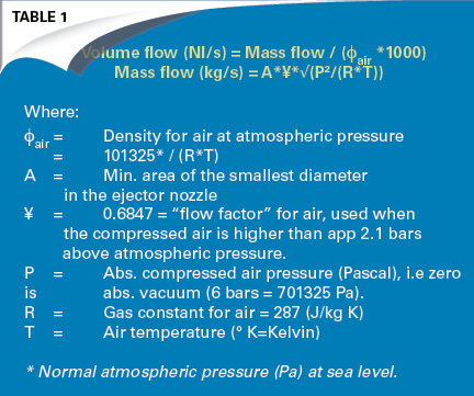
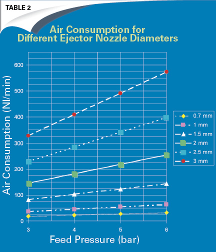
It is quite common that the specified air consumption for ejectors will differ from the theoretic value. The actual air consumption should be very close to the theoretic value (the difference of a few percentage points is reasonable.) Table 2 demonstrates the theoretic value for some common nozzle diameters at varying feed pressures. Calculations are made at a temperature of 10°C (283.16 Kelvin).
The other, and quite often forgotten, energy thief in a vacuum-handling system designed for sealed materials is the blow-off function, which is used for quick release of the object. The air consumed during blow-off is determined by the flow capacity of the valve that controls the function and pressure being used. When utilizing a large, centrally placed ejector (i.e., many cups connected to the same source), very high levels of flow are required in order to quickly break the seal on remotely placed suction cups. In this case, flow levels in the range of 200-500 Nl/min at 4-6 bars are standard.
In a decentralized system using one small ejector at each point-of-suction, the release function is, in many cases, the result of blocking the exhaust. The air traveling through the ejector will be forced into the cup, so the air consumption will be equal to, or slightly higher than, the air consumption for producing vacuum. An alternative solution is a small blow-off check valve on a decentralized unit, which typically allows 100-200 Nl/min to pass through at 4-6 bars.
In order to calculate the energy consumed, it is required that the compressor efficiency is known. A normal-sized compressor, able to create 7-10 bars of pressure, consumes 6-10 kW per produced cubic meter of air, depending on size and efficiency. The total air consumption for an ejector system per year can easily be calculated by adding the air consumed by vacuum production and the air consumed by blow-off function in each cycle, and then multiplying by the number of cycles per year. Even better is to measure the consumption with a flow meter over the course of a number of cycles.
An accepted fact is that the CO2 emissions per produced kWh of electric power will be as follows, depending on the type of production:
- Gas: 0.2 kg CO2/kWh
- Oil: 0.27 kg CO2/kWh
- Coal: 0.33 kg CO2/kWh
- Nuclear, Wind, Hydro: 0.0007 kg CO2/kWh
Re-calculated for compressed air production, the result is 0.02 – 0.033 kg CO2/m3 if only considering the “dirty” production methods and basing the compressor efficiency on 10 kW per produced cubic meter of air.
How to Reduce Vacuum System Carbon Footprint to a Minimum
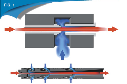
The ejector’s efficiency is obviously an important parameter to focus on when attempting to minimize energy/air consumption. Ejector efficiency is determined by the vacuum performance (flow and speed of evacuation) in relation to air consumption. Basically, there are two main types of ejectors used in sealed vacuum-handling systems today: single-stage ejectors and multistage ejectors (Fig. 1). The multistage design is more complex and requires more space, but it will always be 15-50% more efficient (same speed/response time with less energy consumption). Therefore, it is important to use a multistage ejector whenever possible.
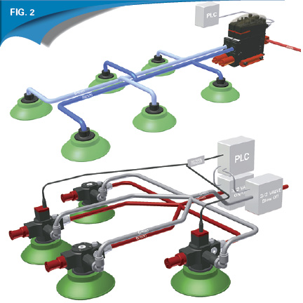
When ejector technology entered the market for vacuum material handling of sealed parts and started to replace electrical-driven vacuum pumps, the main reasons were the simplicity and reliability of the products, as well as the ability to easily control the ejectors’ power during operation. At that time, small ejectors were placed on each suction cup, forming a decentralized system. In many cases, a decentralized system such as this is the most efficient system, as it places suction exactly where it is needed. There is no need for over-dimensioned ejectors to compensate for losses and extra volume. There is also a reduced risk of leakage from fittings and couplings.
However, when air-saving technology became available for ejectors, a new trend began. So-called “compact ejectors” (or “smart ejectors”) with integrated control functions, such as valves, vacuum switches, and air-saving functions, flooded the market. These compact ejectors are centrally placed and serve several suction cups. They are usually located a few meters away from the points-of-suction. The air-saving function turns the ejector off when enough vacuum pressure is created, and turns it back on to compensate for any leakage occurring in the system. One major advantage of this system is that the centralized ejector with air-saving function only works for a short period of time during the vacuum-duty cycle, and energy will be saved when compared to the previous decentralized concept (Fig. 2). With the centralized compact ejectors, factors like operational reliability and safety (one ejector per cup), as well as speed of vacuum generation and object release, must be sacrificed to a certain degree. Speed can be compensated for with a very large centralized ejector, but this means much greater energy consumption.
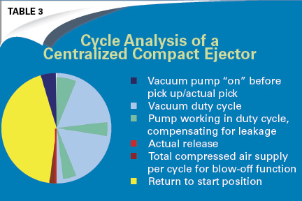
Another issue in utilizing centralized compact ejectors is that the blow-off function has to be very powerful in order to release parts quickly enough. This is because pipes are long and often restricted, leading to large amounts of air consumption during the time needed for blow-off. Table 3 shows a typical work cycle in a sealed vacuum-handling application utilizing a compact ejector with air-saving function.
Air consumption occurs during the following phases:
- Dark blue: Vacuum is started in the system before the actual pick to increase pick-up speed.
- Blue: Enough vacuum is made in the system to compensate for leakage from fittings and couplings. A few recoveries per cycle are not unusual due to leakage.
- Red: Object release using positive pressure blow-off
- Dark red: Excessive blow-off time
It is obvious that even with an air-saving function in place, there will be a great deal of compressed air consumed during each cycle.
Can Air Consumption and Carbon Footprint Be Substantially Reduced?
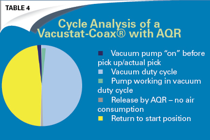
A new, compact, decentralized ejector unit with two unique features is the answer to the question of whether or not air consumption and carbon footprint can be substantially reduced with a vacuum system. The two features are the fully pneumatic and internal air-saving device called Vacustat and a new release valve (AQR), which uses the ambient atmosphere to quickly release a handled part. The volume of a single suction cup is so low that atmosphere air is all that is needed. In other words, no compressed air is needed for release, and an automatic air-saving device is in place.
This concept offers all the benefits of a decentralized ejector system in terms of reliability, safety, and speed (response and release). The air and energy consumed is virtually nonexistent. There is no compressed air consumption during the release of objects, and the air-saving function does not have to compensate for leakage from multiple fittings and couplings. The volume is so low that the air-saving function will start almost instantly. Time that the ejector must be on before pick-up is also reduced to almost nothing, and there is no need to create a pre-vacuum in the system. It will be fast, regardless.
As Table 4 highlights, the pump is only working for an extremely short period of time.
Now we will look at a typical sealed vacuum-handling application with the following conditions and requirement:
- Cycle time: 10 s
- Working hours per year: 6,000 h
- Vacuum duty cycle: 5 s
- Diameter 75-mm cups: 4 pcs
- Response time: max 0,1 – 0,2 s
- Release time: < 0,1 s
- Previously developed decentralized solutions use approximately 25,000 – 40,000* m3 of air per year.
- A compact ejector with air-saving function will reduce air consumption to approximately 15,000 – 20,000* m3 of air per year.
- The Vacustat-COAX®-AQR solution will use about 1,000 m3 of air per year.
* Range varies greatly, as it depends on whether single or multistage ejector technology is used.
Under these conditions, it is possible to reduce energy consumption by 90-99% by simply using the latest available technology.
Returning to our previous equation, we can calculate that 15,000 – 40,000 m3 of air corresponds to approximately 450 – 1,200 kg of carbon-dioxide emissions if the electrical power is supplied by a coal, oil, or gas plant. This is based only on a single application/station. A typical automotive plant can have up to 400 of these applications in operation. The carbon footprint of vacuum handling in these plants can be between 180,000 and 480,000 kg when utilizing traditional vacuum technology (based on conditions above). When utilizing a Vacustat-COAX® with AQR technology, the carbon footprint can be reduced to only 12,000 kg.
In comparison, the average amount of CO2 emitted from one car is 180 g/km. The reduced carbon footprint an automotive plant can achieve per year by using the latest vacuum-handling technology corresponds to 933,333 – 2,600,000 km of driving.
About the author: Josef Karbassi is vice president of the Automation Division for Piab. For more information, visit www.piab.com.
Reinforce your industry expertise with a Pneumatic Mechanic, Technician, or Specialist certification. Apply online at www.ifps.org.
Share this information.
Related Posts

Sponsor

Sponsors