Safety Catchers
The Sitema safety catchers from Advanced Machine & Engineering Co. (AME), Rockford, Ill., stop and lock a dropping platen via a wedge mechanism located on a smooth rod that can be placed in any position and that is activated by the weight of the dropping mass.
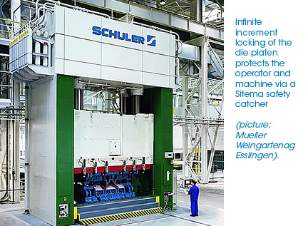
Some machines are equipped with safety devices that operate in only one or a few positions, such as interference rods or linkage mechanisms. The upper platen must travel the full stroke even if a fraction of the stroke would be sufficient for production reasons. With such devices, total safety cannot be guaranteed. If, for example, an emergency stop or a power failure occurs in the middle of the full stroke, the latching device cannot be activated. With multiple-ratchet-position devices, it is questionable whether or not the ratchet will properly engage and withstand the forces of the dropping mass.
Installing safety catchers on hydraulic presses and other machines in which dropping masses are a concern can eliminate such dangers. Infinite position locking is an advantage. These safety catchers lock the mass to a smooth round bar.
The safety catchers can be used not only on hydraulic presses, but also on any other machines or devices in which dropping masses must be stopped for safety reasons. They include vertical-axis devices of machine tools, portals, material-handling systems, and platforms in theaters or amusement park rides.
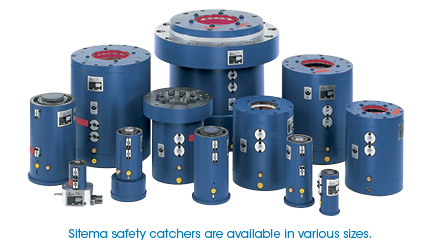
The safety catchers are certified by the German TÜV to comply with DIN EN 693 standard as lift-secure devices. Other certifications also are available upon request. Exotic clamping problems also can be solved with Sitema special devices for low- or high-quantity applications to satisfy even those customers with complicated requirements.
The high degree of safety in tandem with a productivity increase is achieved as follows:
1. The load is secured by stopping the dropping mass using the weight as a means to wedge the safety catcher against the acting hydraulic cylinder rod or a separate catcher rod. The locking capability is proportioned to the dropping mass: the heavier the dropping mass, the stronger the grip.
2. The locking position functions for the entire stroke of the machine, which guarantees a safety stop at any stroke position. Productivity loss as a result of positioning the platen to a certain point to interlock the safety device is eliminated.
3. Depending on the device type, the locking system is held open by either hydraulic or pneumatic pressure. Whenever the pressure drops, the safety catcher is set to automatically secure any dropping load.
4. The full-locking force is created only by the load. The unit will lock only when the safety catcher is in the locking position (no hydraulic or pneumatic pressure is present) and the load is moving downward (such as when the acting hydraulic cylinder of the press is leaking).
5. Stopping the movement of the dropping mass is not an issue with proper safety catcher selection. Mass deceleration generally is 1-3 g.
6. The proximity switches signal “load secured” or “unlocked.” They can be used for the machine control.

