Sizing Tubes for Hydraulic Systems
Tubing must meet two requirements:
- The inside diameter must be large enough to provide the flow area needed to assure that fluid velocity does not exceed the limits set by the SAE.
- The wall thickness must be large enough to meet the strength required by the applied pressure and the ultimate tensile strength of the tubing.
The first requirement is satisfied when the inside diameter is at least ID, inches = 0.639 (Vmax / Q)1/2 where
- Vmax for pressure lines = 15 ft/second
- Vmax for return lines = 10 ft/second
- Vmax for suction lines = 4 ft/second
- Q, gpm is the fluid flow rate
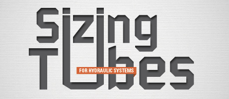
Values of inside diameter as a function of flow rate are shown in Table 1. The calculated inside diameter for a given flow rate may not satisfy condition #2 for strength.
Three formulas are used to determine the wall thickness for strength:
- Barlow formula, P = 2 ST/D
- Boardman formula, P = 2 ST / (D – 0.8 T)
- Lamē formula, P = S (D2 – d2) / (D2 + d2)
where
P = maximum working pressure, psi
D = tube outside diameter, inches
d = tube inside diameter, inches
T = tube wall thickness, inches
S = allowable stress, psi = Sult / F.S.
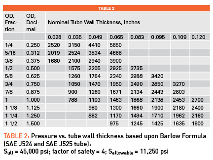
 Formulas 2 and 3 are dependent upon the inside diameter, while formula 1 is not. It can be seen that the Boardman formula is less conservative than the Barlow formula. The Lamē formula is intended to be used for thick wall tubing, defined as tubing having a wall thickness that is 10% or more than the inside diameter. While the Lamē formula might be appropriate for high-pressure systems, the Barlow formula is often used in sizing tubing. Table 2 is based upon the Barlow formula.
Assuming Sult = 45,000 psi for SAE J524 and J525 tubing and a factor of safety of 4, the allowable stress is 11,250 psi. Table 2 gives the maximum pressure allowed for different common wall sizes. Tubing conforming to SAE J524 or SAE J525 must satisfy both Tables 1 and 2. The allowable pressure values in Table 2 will increase if higher-strength tubing is used.
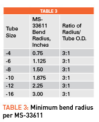
A third consideration in selecting the best tube wall is how readily it can be bent. Thin wall tube is known to sometimes buckle on the inside diameter. This may limit the minimum wall thickness, even though it is theoretically adequate in strength. The tubing should be well supported by the bending tool and should not be bent to less than standard bend radius. Both SAE J524 and SAE J525 tubes are annealed to facilitate bending and flaring. There is usually an oval section created in the bend. Some allow a maximum oval of 5%, while others insist that the oval section not exceed 3% of the tube outside diameter. Strength of tubing will be reduced by both an oval section and thinning of the wall on the outside of bends.
A final caution reminds us that SAE J524 and SAE J525 tubes are made of carbon steel. They will corrode in corrosive environments if not protected by paint. Corrosion will also reduce tube strength.
By G. K. Fling, P.E., CFPS, Southwestern Controls




There appears to be an error in the top formula for tube ID calculation: variables Q and Vmax are inverted. I believe nominal tube ID is proportional to flow and inversely proportional to velocity.
I agree with Brian. I also found recommendation from most literature I referred; the V-Max (pressure line_ is 25FT/S; not 15FT/s
1000 ton capacity calendar in pipe id