Vertical Integration: Electronic Load Sensing for Hydraulic Pumps
By Neil Skoog, CFPS, Project Developer, ERHCO.
 Load sense control of open circuit variable displacement piston pumps has contributed significantly to reducing energy consumption in hydraulic systems. This is especially true for mobile hydraulic systems that have widely varying load and speed requirements punctuated by periods of standby where no work is done.
The known benefit is that a pressure compensated variable displacement pump operates at a low standby pressure when no functions are active. When a function operates that requires less than full flow and pressure, the pump produces only the required flow at a pressure slightly higher than the actual load pressure. Typical hydraulic courses have graphs showing the power savings when compared to a fixed displacement pump or a variable displacement pressure compensated pump operating at compensator pressure when the theoretical output load pressure and flow requirement is less than the pump capacity. These examples only show the potential energy savings when one pump controls one actuator. When one pump supplies multiple actuators operating at different pressure and flow requirements, any potential energy savings rarely matches the optimum value provided by the classroom example. Interconnecting multiple pumps to work together can also be challenging.
Load sense has become so widely accepted that many manufacturers have valves designed specifically for load sense applications. The valves have a series of internal shuttle valves to send the highest load pressure requirement to the load sense output port. The typical valve also has ports to “daisy chain” load sense signals from other valves, so the highest load pressure requirement supplies the load sense port on the pump. The valve at the end of the daisy chain bleeds off the load sense pressure when no valve is actuated.
There are several drawbacks to load sense control that make applying it challenging in some applications. The main issues relate to the load sense feedback line itself. You typically use a 1/4-inch (6-mm) or 3/8-inch (10-mm) diameter hose. In cold environments, the oil in the line can be highly viscous and fail to produce an adequate signal to pump. Also, on large machines with multiple valve locations over long distances, the time delay for the pressure signal to reach the pump load sense port results in sluggish reaction. If the load pressure changes increase and decrease too quickly, the pump overcompensates and causes instability. A common solution is to add a bleed orifice at the pump for a small continuous flow that keeps the fluid warm and less viscous. The orifice also helps dampen pressure spikes, allowing the pump to respond in a more stable manner. This bleed orifice can require an increase to the load sense line to accommodate the associated pressure drop. Occasionally flow controls with a bypass check are added to the load sense circuit to stabilize the system. In extreme cases, accumulators are also utilized.
As electrohydraulic proportional directional control valves with related digital controllers become more popular, the possibility of using electronic load sensing also becomes more practical and offers other advantages. While you can use electronic load sensing with manually operated valves, it may not offer some of the additional benefits.
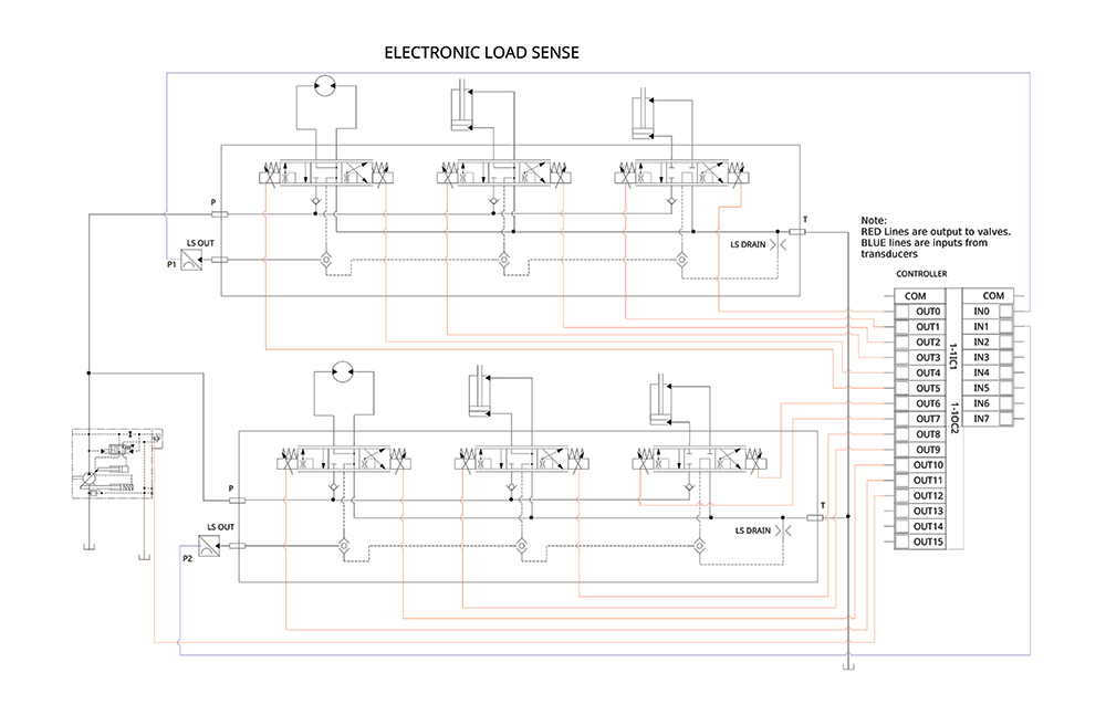
Electronic load sense control is accomplished by replacing the load sense feedback line with pressure transducers at each valve. Instead of daisy chaining multiple valves together, each valve can have its own dedicated transducer. Each transducer sends a signal to an electronic control module. The pump control changes from a load sense control, which requires a pressure signal to the load sense port, to a remote pressure control that sends a pressure signal to a remote relief valve. The remote relief valve then adjusts the compensator pressure to match the load pressure up to the main pump compensator setting. The proportional pilot relief is controlled by the same electronic controller that is receiving the signal from the multiple pressure transducers. Simple systems with minimal outputs or manually operated valves may only require one controller for the entire machine. For complex systems requiring multiple transducer inputs, multiple proportional directional valves, and more than one pump control output, it may be more practical to use a dedicated controller for the load sense functions. The program evaluates the pressure transducer inputs, then outputs the highest pressure command to the pump pilot pressure control. Many remote proportional controls on the pump still have some form of a differential spring; or you can add a differential pressure to the control signal.
The first benefit of electronic load sense is the almost instant response of a pressure signal. Cold viscous oil, excessive line lengths, or the capacitance of the pilot line do not affect the signal.
Electronic load sensing can provide variable differential settings. The common load sense control on the pump has a fixed differential or standby pressure setting. It can be tuned during commissioning, but it is typically not adjusted after that. The nominal pressure can vary from 15 to 35 bar (220 to 500 psi) depending on the pump and valve requirements. When a bleed orifice is installed, the flow-pressure drop also affects the differential setting and pump response. The electronic load sense control responds not only to the pressure signal, it also provides a differential pressure that responds to the valves being commanded. In one application, a feed cylinder had to be limited in the retract force. In this case the cylinder was the only function active for that part of the cycle. Limiting the pilot pressure when that specific function was actuated to retract the cylinder limits the retract force. An added benefit was that the load sense pressure was also mapped to the retract command. A slight command increases the pump pressure setting slightly; the higher the operator command, the more the proportional directional valve opened and the pump pilot pressure increased. This resulted in a unique feathering ability to retract the cylinder.
Another benefit is the ability to ramp or delay the load sense pressure command at the pump. One application has a high standby pressure, nominally 35 bar (500 psi). When a function actuates, the differential pressure gradually lowers to 15 bar (200 psi) over the load pressure. The result is fast response when the valve shifts, followed by reduced pressure drop across the valve when the function is operating and the flow is higher.
Fan applications using load sense pressure compensated pumps often result in oscillation that requires considerable tuning. The challenge is that the oscillation is related to the pressure spiking when accelerating the fan, then dropping because the pump compensates at the same time the fan motor begins turning, and the fan inertia keeps the motor spinning. This oscillation can be alleviated by ramping the control pressure up relative to the commanded fan speed instead of the pressure. Since fans have a characteristic speed-torque curve, it can be programmed into the control without too much difficulty.
Because electronic load sensing uses a remote pressure control on the pump, a sophisticated control that calculates the flow requirements based on the summing proportional valve command values and the load pressures also provides a form of power limiting.
If an application requires a failure mode to ensure the functions can still operate, an inverse proportional relief can be used for the pilot control. The inverse proportional relief operates at full pressure with no command and reduces pressure as the command increases. The default condition causes the pump to operate as a simple pressure compensated pump if the load sense control program experiences a failure, such as a broken wire or other damage.
Electronic load sensing offers control options that in the past were either impractical or impossible. By combining the faster processing speeds of modern controllers with added I/O capacity, electronic load sense control optimizes the differential pressure of a conventional load sense system. Electronic controllers can now integrate system pressure with flow requirements to provide power-limiting features for a specific application. •
Share this information.
Related Posts
Danfoss Launches Aeroquip Dynamax Hose Line

Utilization of Sensitive Compliant Lightweight Robot Arms for Hydraulic Valve Assembly
Case Study: Building an Industrial Hydraulic System

Pneumatics and Machine Design
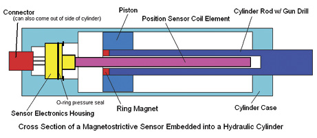
LVIT Sensors and the Future of Proportional Position Sensing in Hydraulic Cylinders
FastLine Marks Four Years Offering Cartridge Valve Assemblies
Sponsor

Sponsors