Stamped: Understanding the acronym and use it for hose assembly
 Proper hose or tubing assembly component selection is critical to a safe hydraulic system. A simple guideline for proper selection is the word “STAMPED”.
Size | Temperature | Application | Material | Pressure | Ends | Delivery
The first step in having a safe hydraulic system is selecting components that meet the needs of the system.
Compromises in hose selection may put others in danger as well as affect the performance life of the system.
SIZE relates to:
• Inside diameter
• Flow requirements
• Assembly length
The inside diameter of the hose must be adequate to keep pressure loss to a minimum and avoid damage to the hose due to heat generation from excessive turbulence. Flow velocity can be determined by calculation, nomograph, charts available from most manufacturers, or reference manuals such as the Lightning Reference Handbook or the Fluid Power Data Book. The recommended flow velocities for most systems are based on system conditions. For example, high pressure at high velocity can incur very high shock loads with quick closing valves in the system. Some practical velocities are:
Pump intake: Less than 1.22 m/s (4 ft/sec)
Return lines: 3.05 m/s (10 ft/sec)
High pressure: 4.57 m/s (15 ft/sec)
Note: The above velocities are recommended based on laminar flow. Most manufacturers agree that excessive velocities within a hose can cause inner lining erosion and if this is combined with contamination, then internal erosion goes up exponentially.
The power transmitted by pressurized fluid varies with pressure and rate of flow. Select hose with adequate size to minimize pressure loss, and to avoid hose damage from heat generation or excessive velocity. Using the general guidelines for line velocities should be done with caution. For example: suction velocities are generally held below 4 ft/sec. to prevent cavitation and possible damage to the pumping equipment. Pressure lines can vary from 10 ft/sec. to 25 or even 30 ft/sec. High velocities however, can be a problem with shock if the circuit has quick closing valves or actuators that stop abruptly. Back pressure in return lines can be a concern with some circuits so it is wise to consider the application before sizing to the guideline.
Hose and tubing are sized to specific flow velocities either by calculation or by chart (see Nomographic Chart in Task 29). These nomographs (or calculations) may be used for sizing fluid passages between hydraulic components when the flow rates are known. Tabulations are based on hydraulic oil having a viscosity of 315 SSU at 100° F.
Pressure losses can vary from charts and tables with changes in temperature, viscosity, ID roughness and number of bends or fittings. It is suggested that the values obtained be multiplied by a factor of two or three to provide an adequate safety margin.
Pressure loss (drop) is also a factor of specific SSU and temperature with a specific gravity of 1.0. To correct for different specific gravities merely multiply the values by the specific gravity of the fluid.
Laminar, turbulent and transitional flows can be a factor but are beyond the scope of this manual.
TEMPERATURE: When selecting a new or replacement assembly two areas of temperature must be considered.
These are fluid temperature and ambient temperature. The hose selected must be capable of withstanding the minimum and maximum system temperatures. Care must be taken when routing near hot manifolds and in extreme cases a heat shield may be advisable.
Caution: To avoid equipment breakdown and possible injury, the fluid manufacturer’s recommended maximum operating temperature for any given fluid must not be exceeded. If the fluid’s temperature limit is different than the listed hose temperature rating, the lower limit must take precedence.
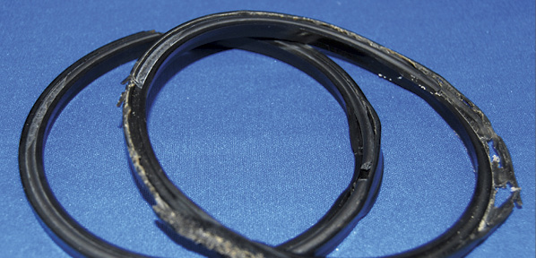
APPLICATION: Determine where the new or replacement hose assembly is to be used. Most often, only a duplicate of the original will be required provided the original hose assembly gave acceptable service life.
Hydraulic hose assemblies have a finite life. Some factors that will reduce life include:
• External abrasion.
• Flexing the hose to less than the specified minimum bend radius.
• Twisting, pulling, kinking, or crushing.
• Operating above maximum or below minimum temperature range.
• Exposing the hose to surge pressures above the maximum working pressure.
• Intermixing hose, connectors, or assembly equipment not recommended by the manufacturer or not following the manufacturer’s instructions for fabricating hose assemblies.
Surge pressures referred to above are rapid and transient rises in pressure. Surge pressures will not be indicated on most common pressure gauges and can be best identified on electronic measuring instruments with a high frequency response.
MATERIAL to be conveyed: Hose selection must assure compatibility of the hose tube, cover, fittings and O-rings with the fluid to be circulated in the system. Additional caution must be exercised for gaseous applications where permeation may occur. Permeation, or effusion, is through the hose pores resulting in loss of fluid. This may occur when the hose is used with fluids such as (but not limited to):
• Air and compressed gases • Liquid, and gaseous fuels
• Refrigerants • Helium
• Fuel oil • Natural gas
If fluids permeate through the tube, consider pin-perforated covers to prevent fluid build up under the cover.
Also consider the compatibility of the system fluid not only with the core tube, but also with the braid, cover, fittings, and other components since permeation may expose the entire hose assembly to the system fluid.
Permeation (effusion) is quite complex and can occur with a great many different chemicals and gases. It should be a consideration in every assembly.
The chemical resistance tables list the relative resistance of hose and fitting materials to the more common chemicals. These ratings do not cover all possible variations of all factors, such as temperature, concentration, degradation, duration of exposure or fluid contamination, etc. Testing under actual conditions is the best way to assure chemical compatibility for critical applications.
Note: O-rings used with fittings must also be considered for chemical compatibility with the fluid to be conveyed.
This includes fittings containing internal O-rings, such as pipe swivels and straight thread O-ring fittings. The manufacturer normally lists the O-ring material in their catalog. Prior to installation, O-rings should be lubricated. (Please refer to manufacturer catalog for recommended lubricants.)
PRESSURE: It is vital to hose selection to know the working pressure including pressure spikes. Published hose working pressures must be equal to or greater than the system pressure. Pressure spikes greater than the published working pressures will shorten hose service life and must be taken under consideration.
Hose manufacturers DO NOT recommend using hose on applications having pressure spikes greater than published hose working pressures.
Burst pressures are reference pressures intended for destructive testing purposes and design safety factors only. Typically, for dynamic hydraulic applications, the minimum burst pressure rating is four times that of the maximum working pressure rating.
Pressure drop must also be considered. This is the difference between the pressure entering the hose assembly and the pressure at the exit end. It will be affected by:
• Friction: The rubbing of fluid against the inside walls of the hose.
• Type of fluid: Different fluids behave differently under pressure. High viscosity fluids are moved with greater difficulty.
• Temperature of the fluid: Higher temperature will cause the fluid to thin and move more easily through the assembly.
• Length of the assembly: The longer the assembly the more surface area friction to decrease pressure.
• Velocity: The higher the velocity the greater the pressure drop.
• Type of fittings and adapters: Any change in flow or direction of flow (such as with a 45° or 90° elbow) can increase the amount of pressure drop.
• Flow rate: Pressure drop increases with increased flow rate for the same size hose.
ENDS of fittings: Identify the end connectors using manufacturers’ catalogs and the information from the preceding chapter.
DELIVERY: Final inspection, special packaging, shipping, and documentation.
Once you have identified STAMPED conditions, go to the manufacturers’ catalogs of choice and select the components required for the hose assembly.
Share this information.
Related Posts

Diagnostic Test Equipment
PRESSURE TRAP B versus D LIP U-SEALS
Filtering Compressed Air to Protect Equipment & Processes
Pressure and Temperature Controls Support Booming Shale Gas Extraction Industry
Productivity in Crushing & Screening: Hydraulic Control and Monitoring
Wireless Pneumatic Solenoid Valve Interfaces
Sponsor

Sponsors