Understanding Hydraulic Stiffness of a System
Hydraulic Stiffness
It is generally misunderstood that hydraulic fluid is incompressible when, in fact, it can compress when placed under pressure.
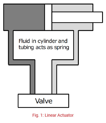 Any system components containing compressible fluid will display the behavior of a spring, and can be treated as a spring, when determining the dynamics of the system. A spring is in effect, a capacitance component, since it can store and deliver power in the same manner as a capacitor in an electrical system.
The stiffness of a spring is determined by the spring constant. The larger the constant, the stiffer the spring.
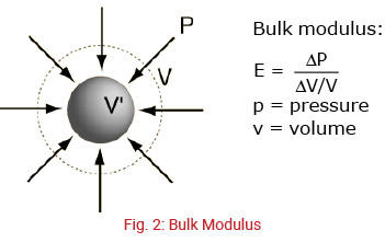
The stiffness of a hydraulic fluid is the ratio of its decrease in volume, as a result of a pressure increase and is given by its bulk modulus of elasticity.
The bulk modulus for hydrocarbon-based hydraulic fluids (E) is approximately 200,000 to 250,000 PSI, which results in a volume change of around 0.4 to 0.5% per 1,000 PSI.
E = ΔP x V / ΔV
E = 2.5 x 10⁵ lb/(in2) = Bulk modulus of elasticity for typical hydraulic fluid
 In any system with high loads, high speeds, and dynamic behavior, the stiffness of the fluid must be considered. The stiffness of the system will impact the response of the actuators to command input from the controlling components. Failure to understand the basic effects of this stiffness can lead to inappropriate selection of control components. In this section, this manual will develop the equation for approximating the stiffness of a linear actuator containing compressible hydraulic fluid.
The actuator in Fig. 3 will behave much like a spring because of the capacitance of the hydraulic fluid. The stiffness of the actuator will be a combination of several factors:
1. The bulk modulus of elasticity of the fluid (E, lb/in2).
2. The area of the piston (A1, in2).
3. The volume of the fluid (V, in3).
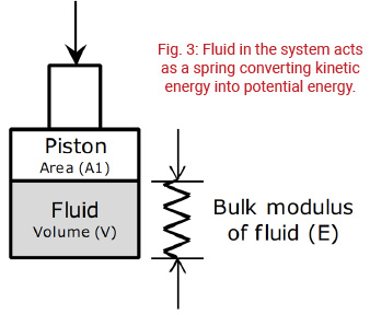 Since the modulus of elasticity is fixed (as long as there is no entrained air in the fluid), the shape of the cylinder in Fig. 3 will determine the stiffness of the component with the stiffness increasing with increasing area, and decreasing with increasing volume. In fact, the stiffness will change as the cylinder extends and retracts.
The stiffness of any hydraulic component can be calculated with the following equation:
Stiffness of a hydraulic actuator
CH = E(A1)2
V
Take particular note of the effect that increasing the area has on increasing the stiffness of the system. The relationship has stiffness increasing as a function of the square of the area. Increasing the area has a greater effect in increasing the responsiveness of a cylinder system than decreasing the length. Note also that stiffness is inversely proportional to the volume of oil in the system.
Example
 Given:
- E = 2.5 x 10⁵ lbf/in2
- Cylinder Bore (piston): 3.00
- L = 3 in
Determine:
Stiffness of the piston on downward compression of the rod from current position
Solution:
A1 = D2 x .7854 = 3.002 x .7854 = 7.07 in2
V = A x L = 7.07 in2 3 = 21.21 in3
CH = 2.5 x 10⁵ 7.072 = 5.89 x 10⁵ lbf /in
21.21in3
Test Your Skills
Given:
- E = 2.5 x 10⁵ lb./in.
- Piston diameter = 1.50 inches
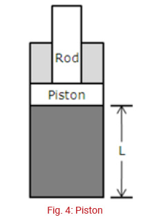
- L = 5 inches
Determine: Stiffness of the piston shown in Fig. 4 on downward compression of the rod from current position.
a. 0.9 x 10⁴ lbf / in.
b. 1.8 x 10⁴ lbf / in.
c. 8.84 x 10⁴ lbf / in.
d. 1.8 x 10⁵ lbf / in.
e. 9.1 x 10⁵ lbf / in.
Find out the solution
C
Share this information.
Related Posts
Klüber Lubrication
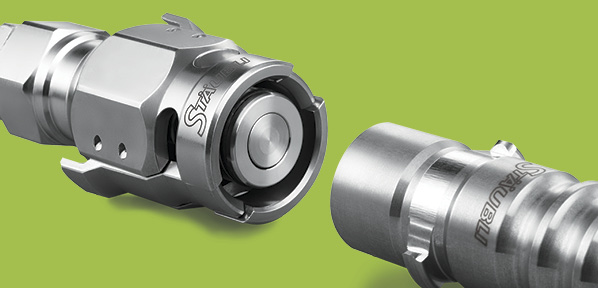
Clean Break, Flat Face, or Double Shut Off?
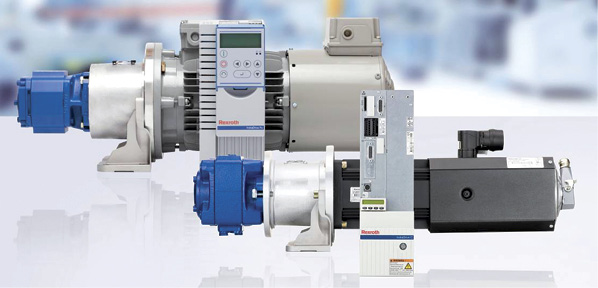
Design Considerations for a More Efficient Power Unit Circuit
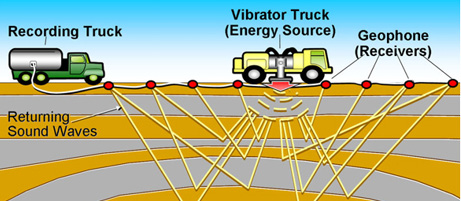
Repairing Hydraulic Servo Valves in Seismic Vibrator Trucks
Top Tips for Specific Types of Heat Exchanger Fouling

Damage Control: Managing Fluid Contamination in Mobile Hydraulic Systems
Sponsor

Sponsors