Understanding Supply-Side Air Preparation
As air is compressed, the temperature of the air increases significantly. The compressor discharge air temperature is typically over 200°F (93°C) for a system operating at 120 psi (830 kPa). Compressed air must be cooled from this high temperature or it would be hazardous. Various coolers are utilized to reduce the air temperature. Air compressors that have two or more stages will have an intercooler between the stages to eliminate some of the heat before the air is fed into the next stage of compression. This improves efficiency. An aftercooler is used to reduce the compressed air temperature. A properly sized aftercooler will reduce the compressed air discharge temperature from 5 to 20°F (2.7 to 11°C) above the ambient air or cooling water. On small compressors, the aftercooler may be a finned tube placed in the airstream of a fan that is an integral part of the compressor drive pulley. On larger systems the aftercooler can be either an air-to-air cooler or an air-water cooler.
The aftercooler should be located as close as possible to the discharge of the air compressor(s). The air-to-air aftercooler is commonly a traditional radiator style or a plate cooler. Sizing the cooler must consider the maximum expected ambient air temperature at 100% humidity. The heated ambient air will need to be vented out of the compressor area.
In the next phase of the conditioning process, the dryer or filter are typically designed to operate at 100°F (37.7°C) or less. If the cooler cannot be sized to lower the discharge air to those temperatures, an air-water cooler or other type of device should be considered. Shell and tube style aftercoolers, consisting of a series of tubes that the hot air flows through with the cooling water flowing around the outside of the tubes in the shell, are commonly used. A water modulating valve is recommended to maintain a constant water temperature and to reduce water flow. The aftercooler will need to be inspected regularly to insure that passageways remain clear. A dirty aftercooler will be less effective, allowing a higher discharge temperature and creating increased pressure drop. The higher the discharge temperature of the aftercooler, the higher the remaining water content, causing the dryer to work harder to achieve the required relative humidity.
 Water removal
As the compressed air is cooled, the excess water vapor will precipitate out, along with small particulates and residual oil from the compressor. The aftercooler, filters, receiver, and additional dryers will have a sump to collect all the condensate. The condensate is primarily water, but because it will also contain particulate contaminants from the free air and residual lubrication oils from the compressor, it cannot be simply drained into a waste-water drain without additional treatment. The sumps will need to be drained periodically to insure proper operation. The simplest drain is a ball valve that maintenance personnel periodically open to collect the condensate for disposal. For systems that have cyclical demand or require frequent draining, an automatic drain can be used. Automatic drains can be simple float valves that open when the sump fills to a preset level, have electrical sensors that open a solenoid valve or use a timer to open on a regular interval, or operate based on air compressor cycle time.
Drain valves will also be required in drop legs throughout the air-supply piping. Sophisticated drain valves are designed to reduce or eliminate air loss during the draining process. Due to the content of the condensate, the drain valves will need to have screens or filters to prevent the condensate from clogging the control orifices and preventing proper operation. The collected condensate must be disposed of in accordance with federal, state, and local environmental regulations. The amount of condensate that must be disposed of in this manner can be reduced by using an approved oil/water separator.
When updating or replacing existing drains, zero loss drains should be used.
 Oil/water separators
The simplest separator is a gravitational separator that consists of a settling tank. The lighter free oil is skimmed off the top and the water is drained off the bottom. If the oil is emulsified in the water, as in the case with some synthetic oils, the water will still contain residual oil. Other types of separators will utilize chemical absorption of the oils while repelling the water. These will also tend to collect the particulate contaminants. Since the oil bonds to the media, the media will need to be replaced on a regular basis. Mechanical separators use coalescing and tortuous path methods to initially separate the oils and may have additional activated charcoal elements to remove oils not separated by the coalescer. Periodic maintenance of the oil/water separator will include changing the elements periodically and cleaning the settling tank to remove residual sludge.
Disposal of any condensate as well as filter elements must be in accordance with federal, state, and local environmental regulations.
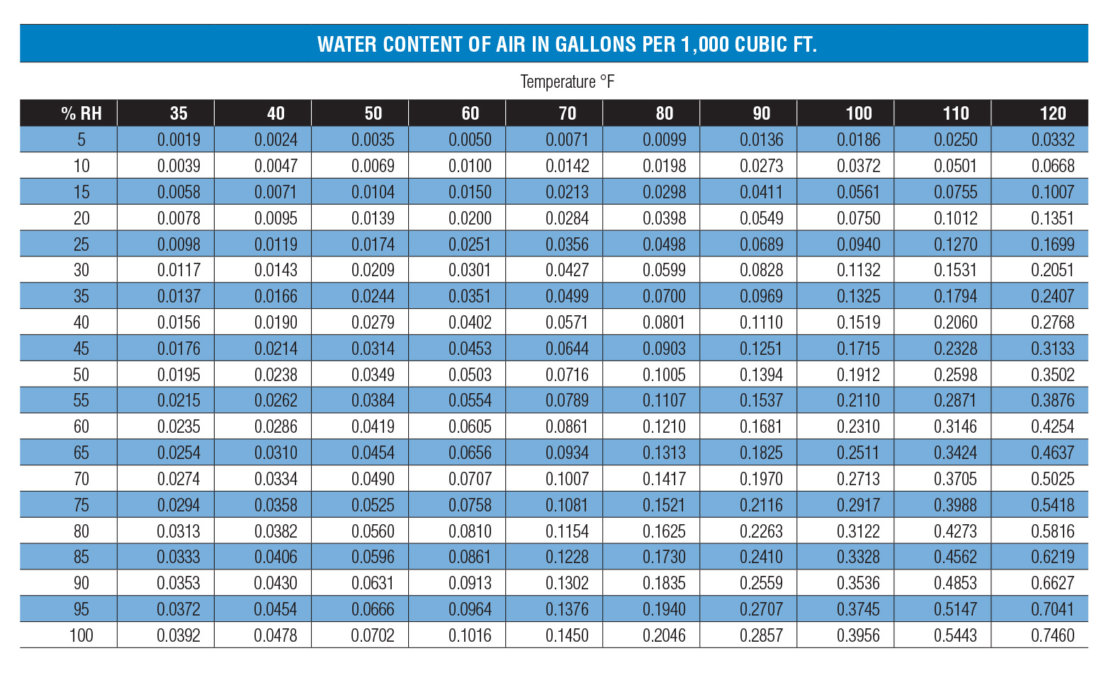
Relative humidity is defined as the amount of water vapor present in air, expressed as a percentage of the amount needed for saturation at the same temperature.
Dew point is the saturation temperature for water vapor in air. If a sample of air is kept at a fixed pressure, but the temperature is reduced, when the temperature reaches the dew point, any additional cooling that occurs after the compressor and before the point of use may cause additional water to precipitate out of the air. The water will act as a contaminant, mixing with lubricating fluids, causing rust and sludge to form that will plug orifices and cause valves and actuators to stick and malfunction. For this reason, additional dryers may be required, after the air leaves the compressor room receiver, just before the final point of use.
Test Your Skills
1. Which one of the following components removes the most water from compressed air?
a. Intercooler.
b. Aftercooler.
c. Receiver.
d. First stage.
e. Inlet filter.
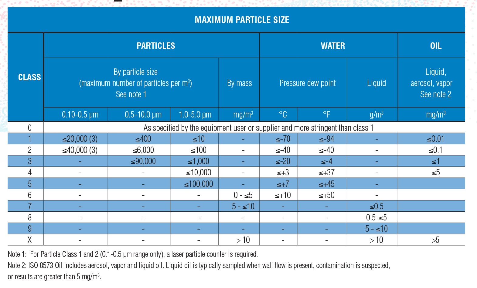
2. What is the ISO 8573-1 recommended dew point for class 3 air?
a. 37.4% relative humidity.
b. -40°F (-43°C).
c. 5°.
d. 68°F (20°C) and 60% relative humidity.
e. -4°F (-20°C).
See the Solutions
1.b, 2.e
Share this information.
Related Posts


Sponsor

Sponsors